It was a year ago I did the majority of the bodywork, finishing with some “nicely”, but not perfectly painted panels. There were a few items that I didnt get too (or didnt have) and a couple that I was not happy with.
Just to finish off this section, here is what I finished / re-worked over the last couple of weeks.
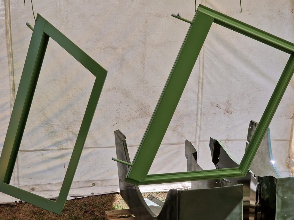
The two wings, i wqas not happy, they were a little rough ontop, so these were treated to a good rub down and finally two top coats, the last one (as before) being a 50/50 mix of Top coat and lacquer.
One bit i had not done last year were the door hinges. These were vapour blasted last year, and kept wrapped up until I was ready to paint again.
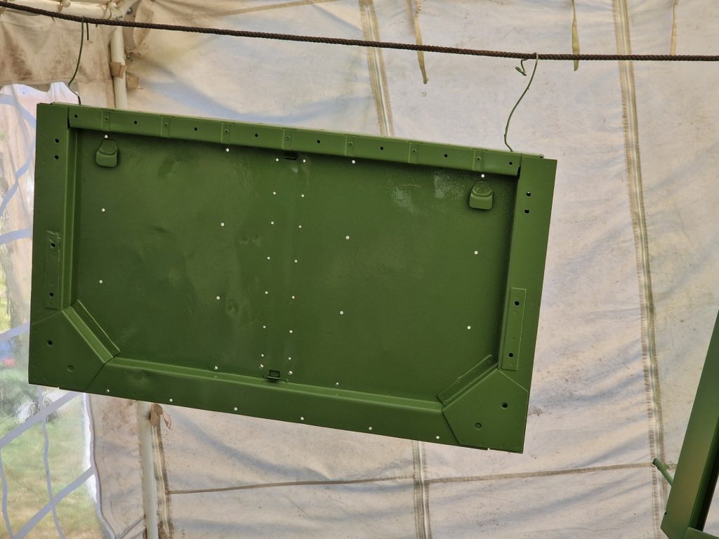
Door tops. The ones on the Land Rover were basically rust, being held together with a little paint. I sourced these new ones from Paintman Panels, along with glazing kit (I saved the original glass).
These were treated to the full pain job, 2 Primer, 2 Undervcoat and 2 top coats.
Tailgate. Isobel came as a hard top, which is fine, but I have my heart set on a softtop, as such was missing a tailgate. This one is not strictly the right one, the hinges (will write that up when I finally get to putting all the newly galv parts on) have three bolts, and should have two, but it will be perfectly fine for me, so this also got the full treatment (twice, as the first time I dropped it onto the grass, so had to re-do it completly)
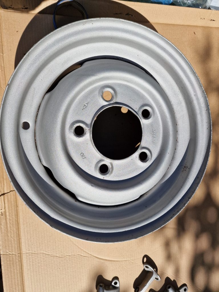
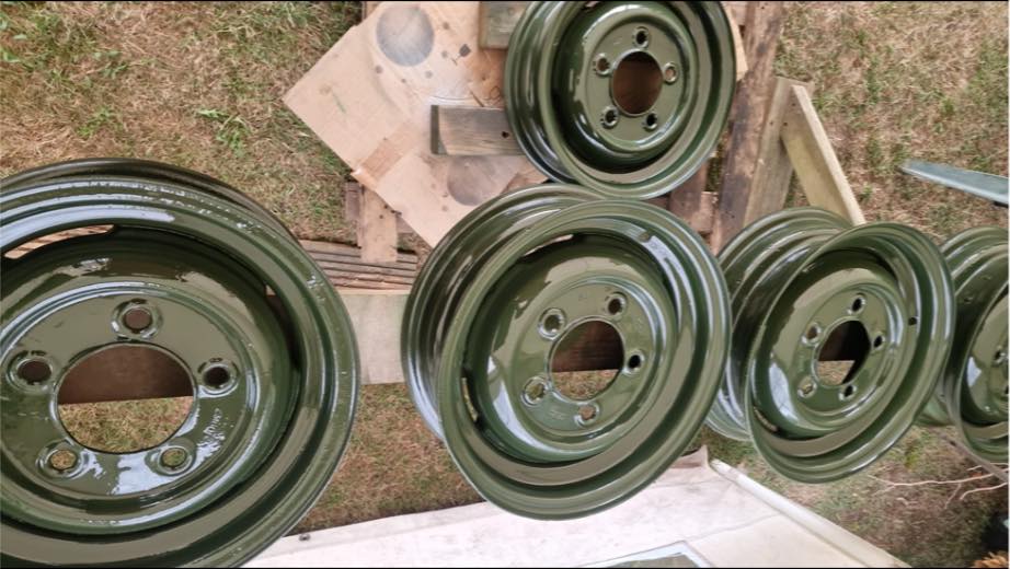
Wheels. Most Land Rovers seem to have the white’ish wheels, but I have gone for Bronze green. My understanding is that this is correct for a Bronze Green vehicle, and I have loads of Bronze Green left over from last year.
First job was to get the tyres removed and then off too Penfolds metalizing to be sand blasted.
That was after of course sorting through the seven wheels to see if I had 5 of the correct rimms, which I do (Part number 231601).
Becuase they were taken back to bare metal, I did etch prime these before starting the painting process.
Not many picutues of the finished items, but here are the wheels before applying the final top coat, I like them.
Thats it, as far as I can think, everthing for the Bodywork is now painted, and ready to be assembled onto the vehicle.
Oh, and I mentioned the front wings. no pictures (I’ve been lazy) but they were re-painted and I’m much happier with them now, will know for sure when they have properly dried.
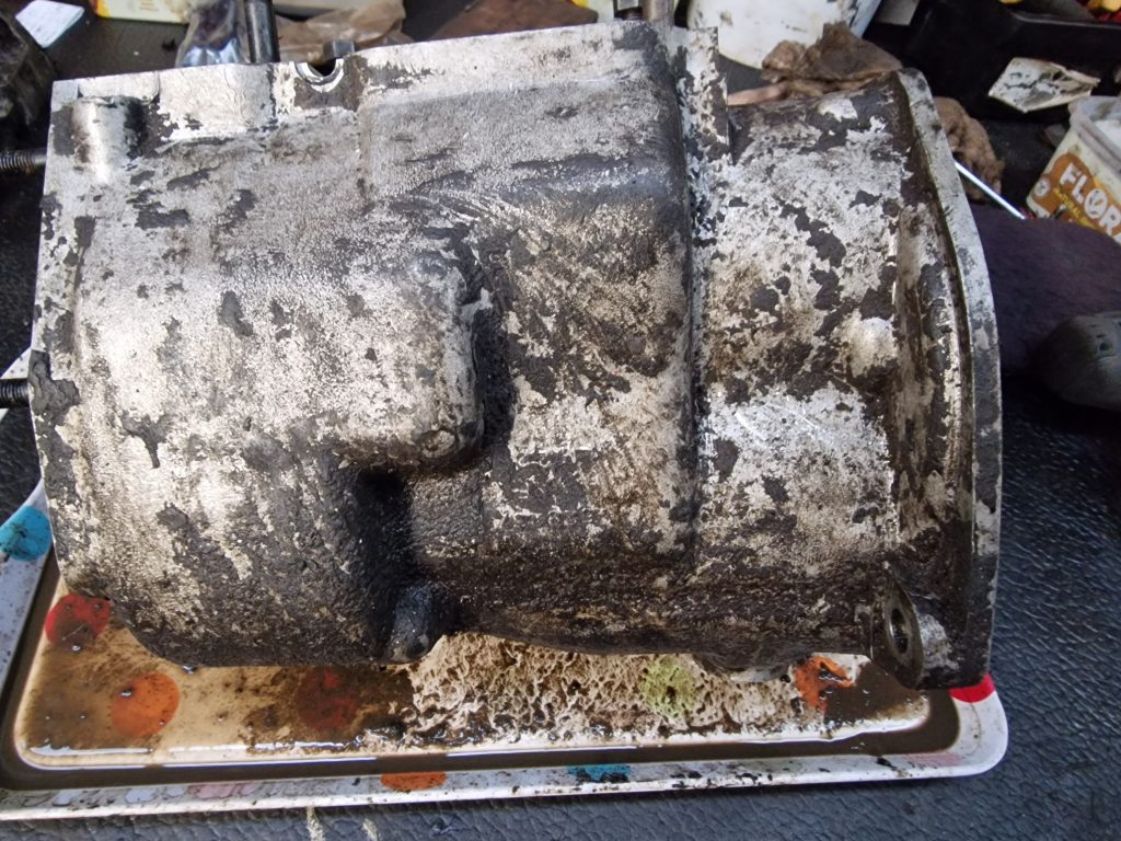
In the last post, I had just got my engine parts back from the engineers, and purchased a few new parts. Before I start putting it all together i thought the best strategy will be to ensure it is all as clean as clean can be.
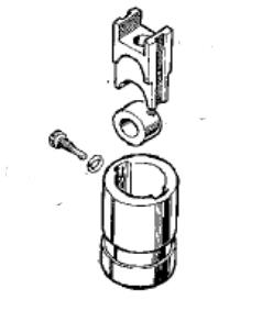
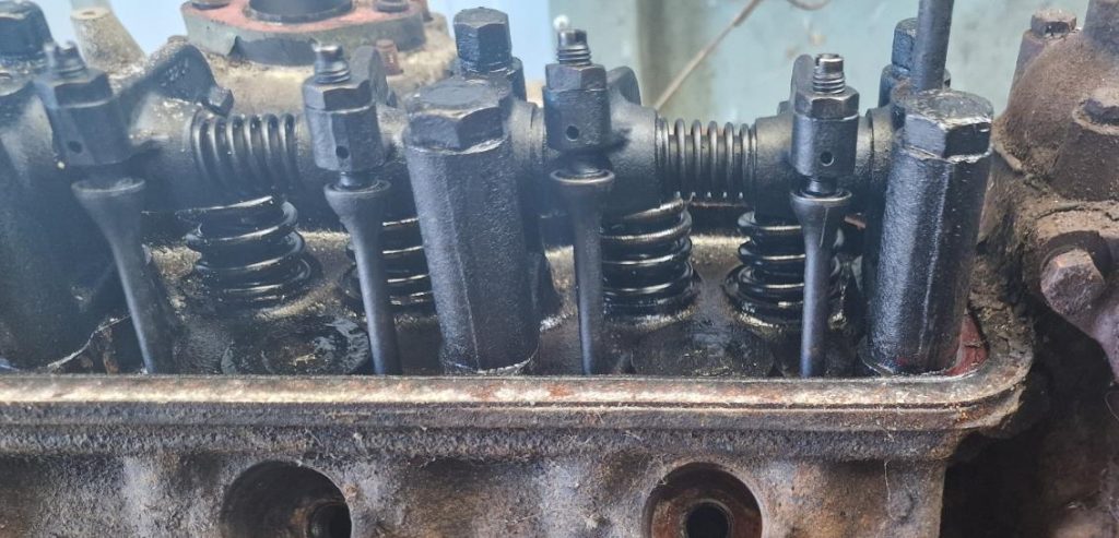
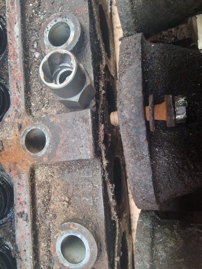
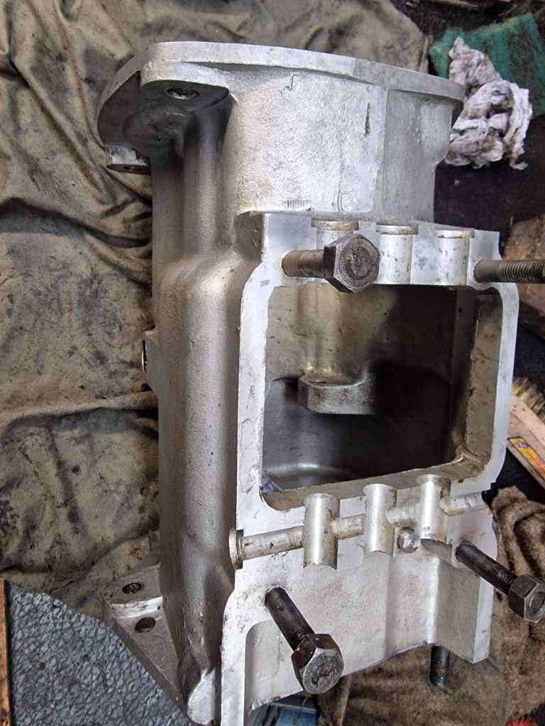
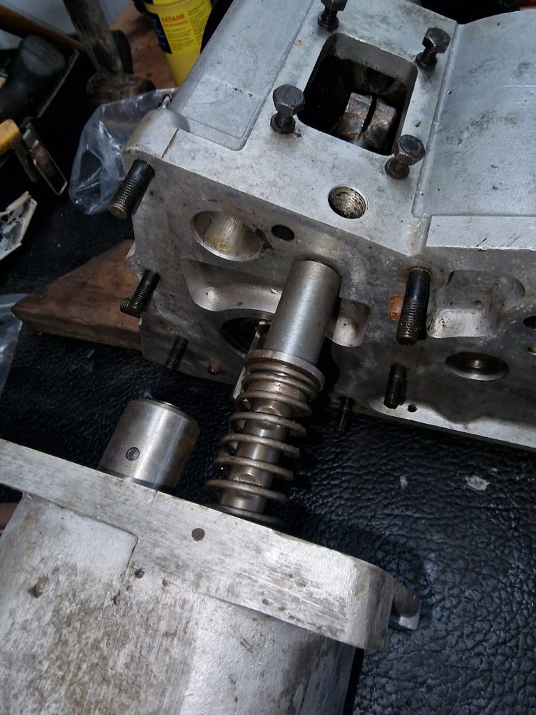
Before I do that, there was something I had not don before it went off to the engineers, a fairly innocuous thing, but as it turned out quite a challenging thing. In the block, the tappets sit inside a tappet guide. I had taken everything off, except the guides.
The tappet is the top part, which sits on a roller which rides on the camshaft. The pushrods for the valves sit in the top of the tappet.
The guide, as mentioned is a push fit into the block and held in position with a special bolt.
Now when you see people put new guides in, they just slide home, so I thought, they would slide out! Nope, could not have been more wrong
To get them out needs a special tool, which is basically a slide hammer, with a bit on the bottom that can slide in, rotate and lift the tappet guide out.
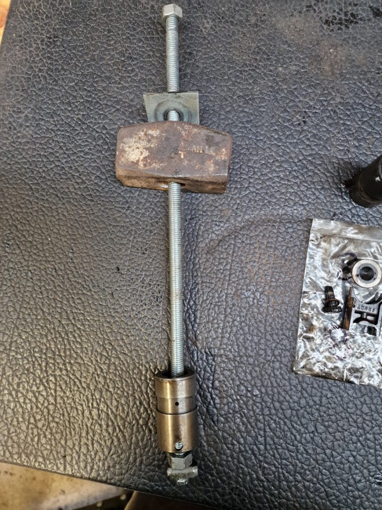
So, not wanting to spend more money on another tool I will likely use 1 time, made this masterpiece.
Basically a bit of 16mm threaded rod, a small “thing” bolted to the end, further secured with a nut, and on the other end the remains of a club hammer.
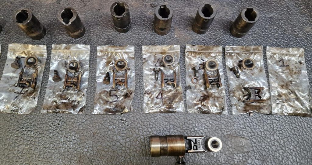
It mostly worked, although did have to modify it for a couple to pull the guides out, which unfortunately resulted in one being broken, so need to replace one.
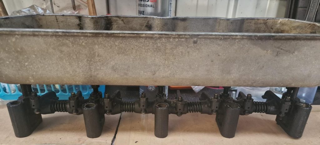
Finally got them all out and inspected. Need to replace all the tappets as quite worn, but the rollers and all but the broken guide are good to go again.
Have to be honest though, half way through I was doubting the decision to take them out. But given they are all caked in old sticky oil, with the oil ways partially blocked, think it was the right decision.
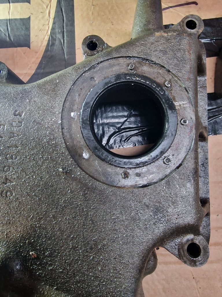
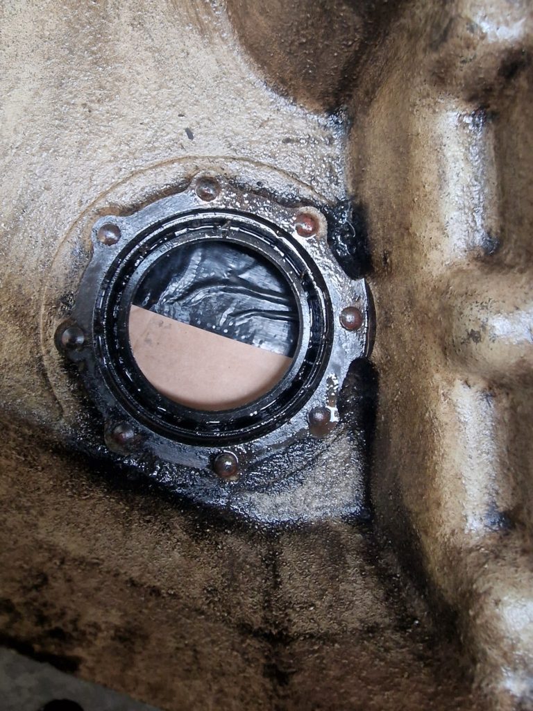
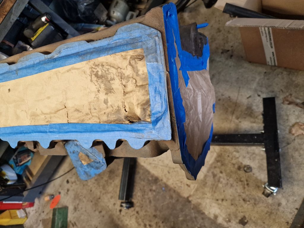
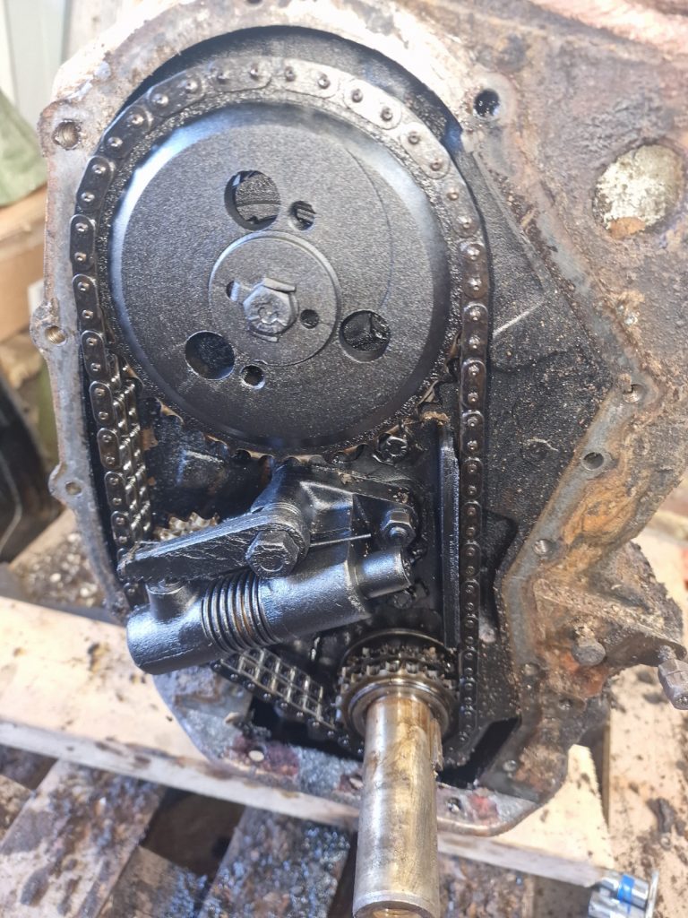
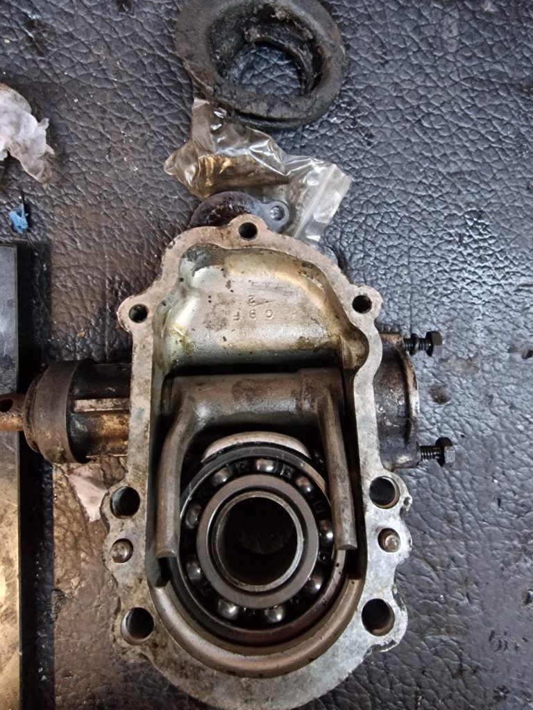
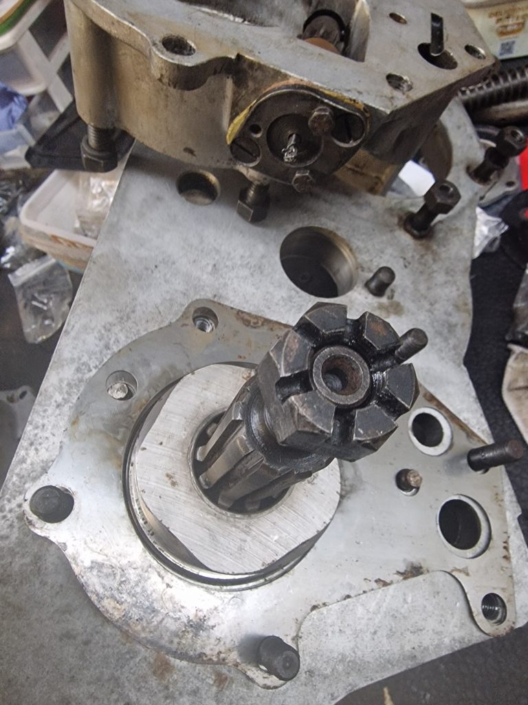
The final bit of disassembly was the front timing cover. While it didn’t go off the engineers, there was a part that I decided to replace, the Oil Seal. I didn’t really think about it when I took the cover of the engine, but realised there is a bit missing. There should be a mud excluder on top of the seal, in the left picture below, so will need one of those. The other odd thing is that this is held on with some sort of rivet. Apparently, when replacing the seal, to put the mud excluder back on requires tapping out the holes in the cover and using self tappers. Will think more about that later, might see if I can source replacement rivets.
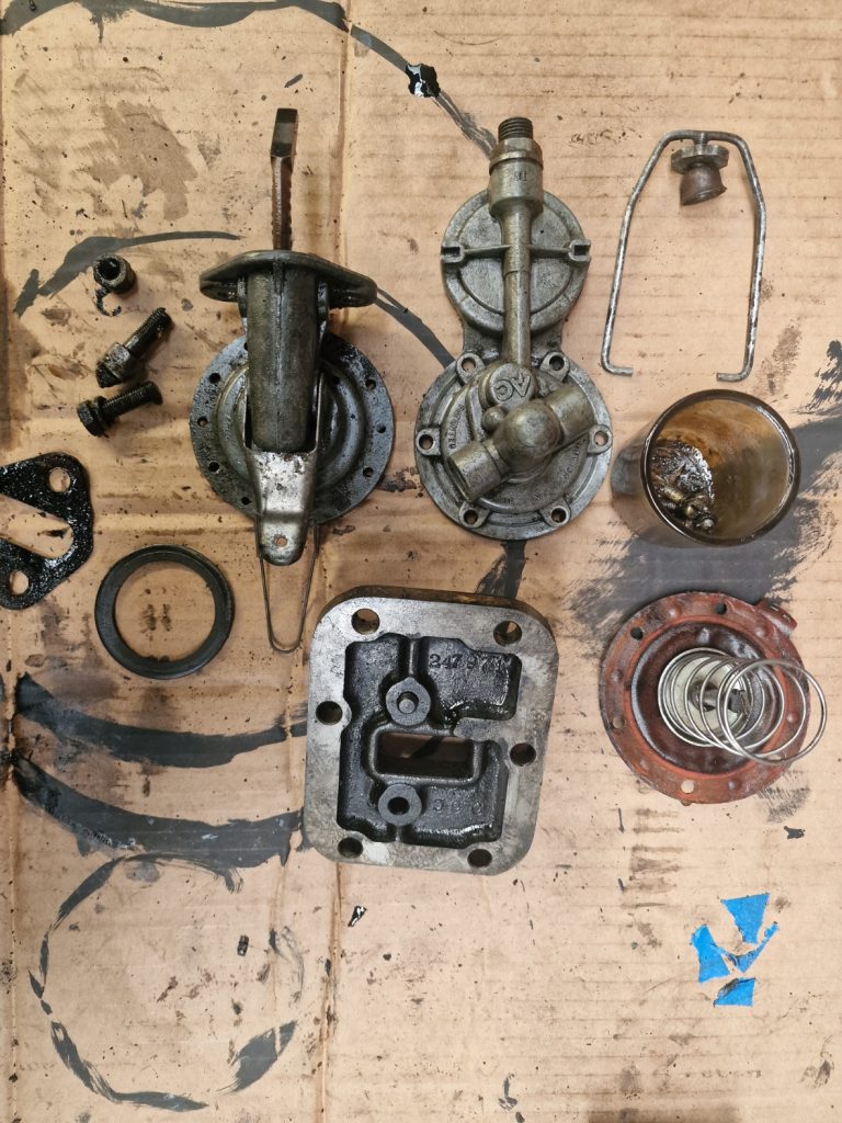
Now I can start cleaning everything, scrapping sticky oil off, scrubbing, de-greasing and then repeat. And while I was at it cleaned up a few other bits also, including the fuel pump, which was covered in old grease and oil.
Not much else to say on this just yet, suffice to say my shopping list is growing yet again.
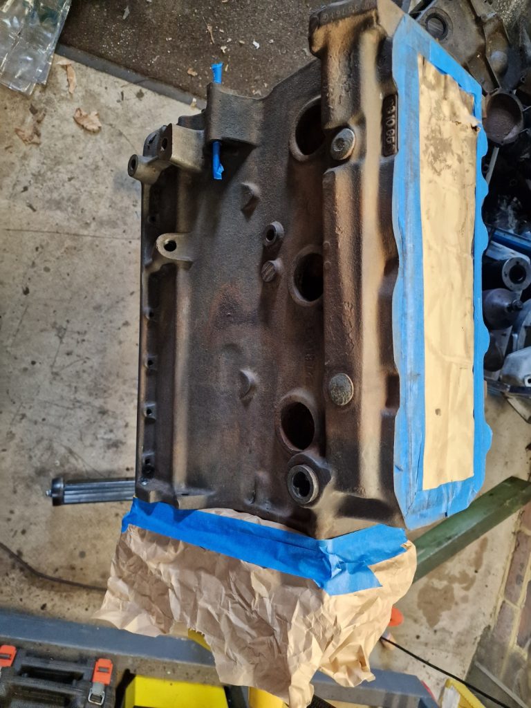
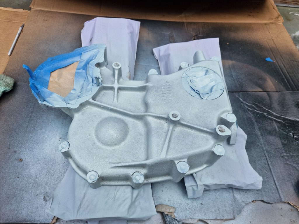
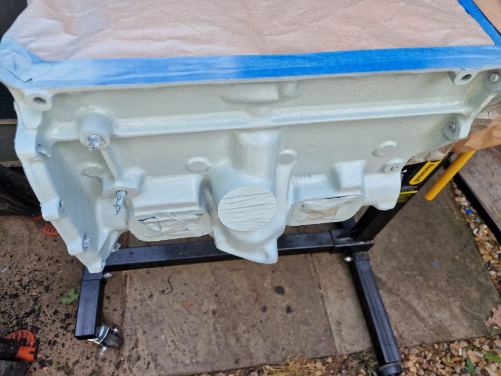
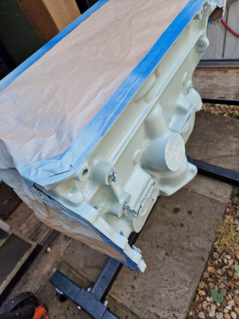
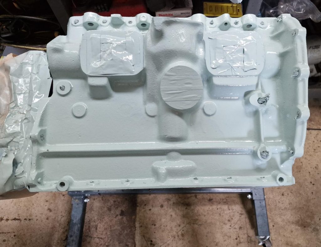
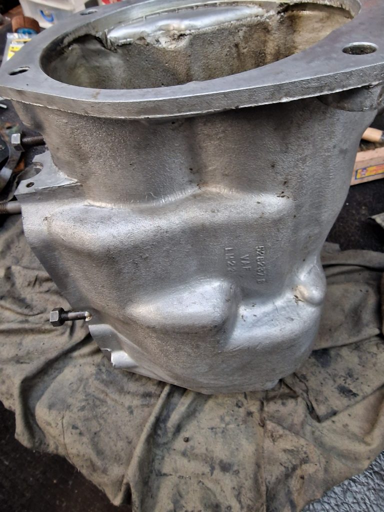
So onto cleaning, and masking up the engine block, head and front cover in preparation for some colour.
And finally some colour. I used Engine paint from Paintman, and should be pretty close to original Land Rover 2.25 Petrol engine colour. While it was not ideal spraying weather, bit windy, I’m happy. Will see what it looks like over the next few days.
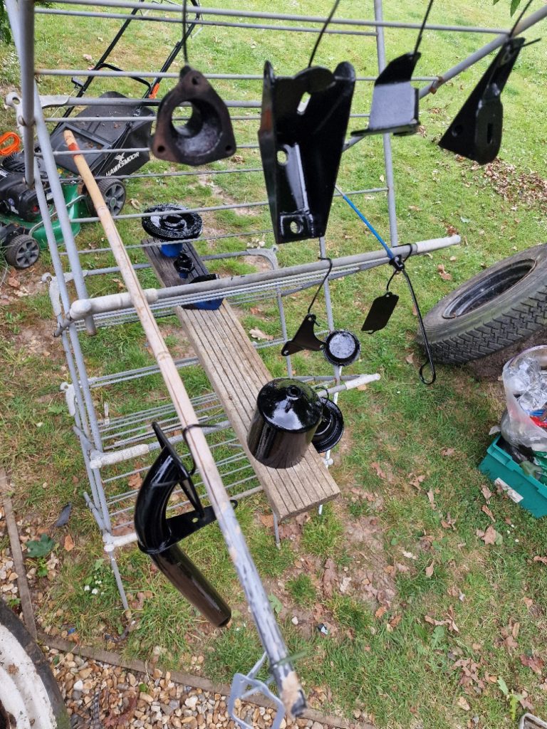
And while I was at it, thought I would paint some of the other engine parts, this time in Shinny Black, again using engine paint, although these parts probably didn’t need it, cant imagine they get too hot.
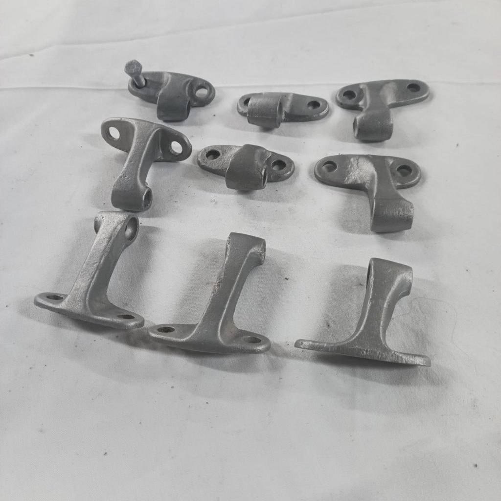
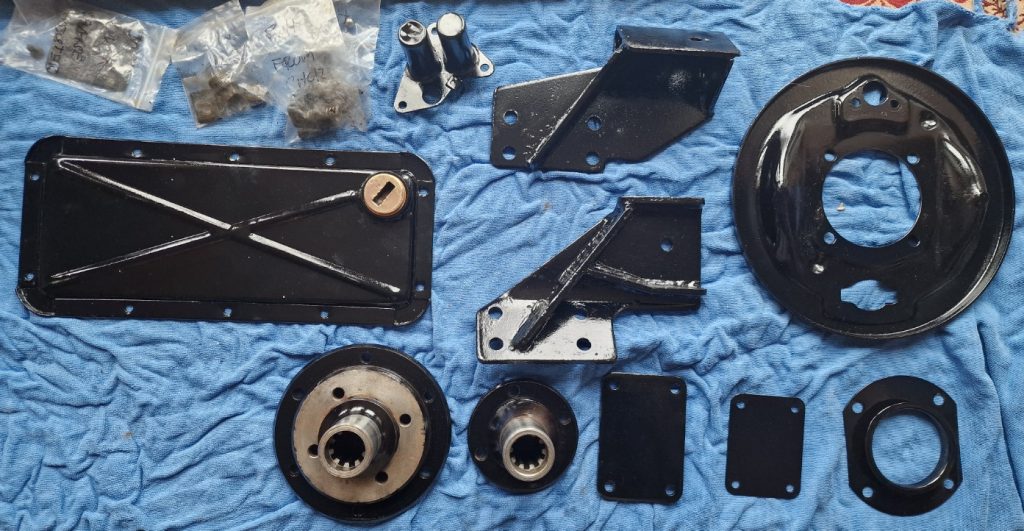
So what have we got here, well starting from the top, Water Pump housing, engine mounts, another bracket (forgotten what thats for at the moment), cover for timing mark on bellhousing, Oil filter case, Oil Filler pipe, Front crank shaft pully, water pump pully.
Think thats about it, oh, not quite, didn’t take a picture but also got some black on the sump.
Not sure if I will be ready to start re-building next weekend, have a few bits to do first, like put in new core plugs, and paint the head (didn’t get that done, ran out of time). Also have decided to replace the camshaft bearings. so will need to hire a special tool for that job, and will write that one up as a seperate post, as I will for the main engine re-build parts, which I think will start with Crankshaft then Pistons and then, who knows? will work it out later.
Its been a while since the last update, and thats for a number of reasons. Had to have a small operation, repair our swimming pool and take down a shed in the garden, due to rodents.
Anyway, back at it again now and while all of that was going on, not been entirely inactive.
In the last update, I had stripped down the engine, and was thinking about what needed to be done.
After a personal recommendation, and reading a number of superb reviews decided to give Banda Engineering a call. Banda Engineering are based in Portsmouth, right near the Navel Base main entrance which I knew well after all the times I dropped and picked up my eldest son when he went on or came back from deployments.
After a brief call, took all the engine bits down, not really knowing what exactly needed to be done. After 5 minutes of Banda taking a look, a couple of measurements later and telling me exactly what needed to be done I was more than happy.
So what was done?
The pistons that came out were original, so possibly could have gone with 020 oversize.
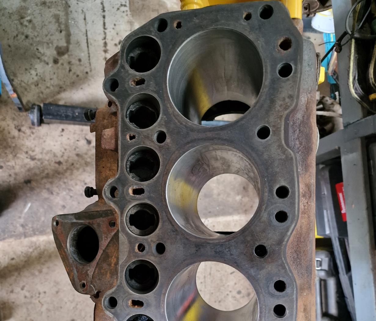
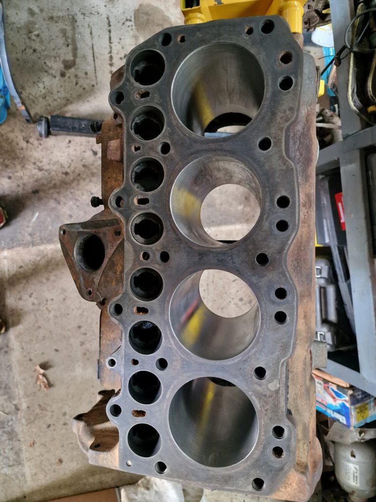
As it turned out, the block was cleaned up a little and re-bored to 030.
Number 4 had a bit of a score mark, probably the reason for skipping 020.
So re-bored and honed, ready for new Pistons.
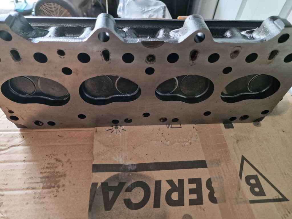
Next, the head. This was again cleaned up, painted and skimmed with hardened valve seats fitted and existing valves re-ground in.
Also, there was a couple of snapped bolts from the manifolds, these were taken out also.
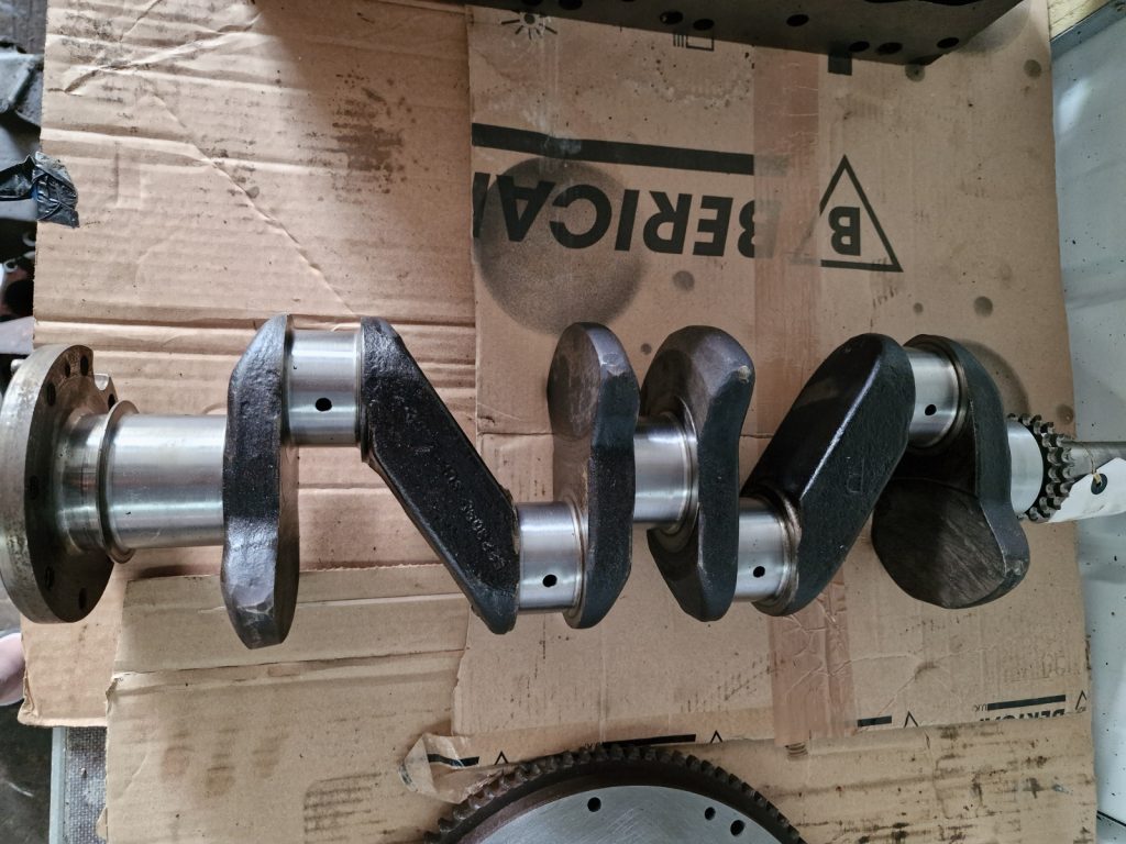
The crank shaft was measured and shown to be in tolerance, so was treated to a polish of the journals.
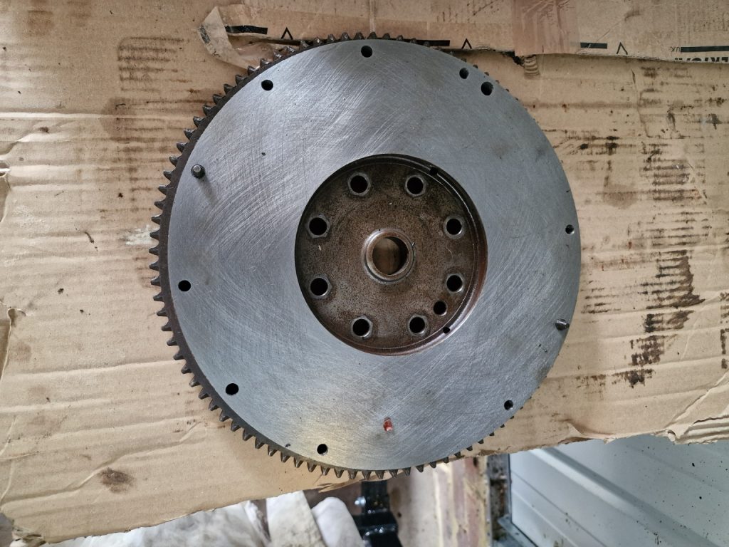
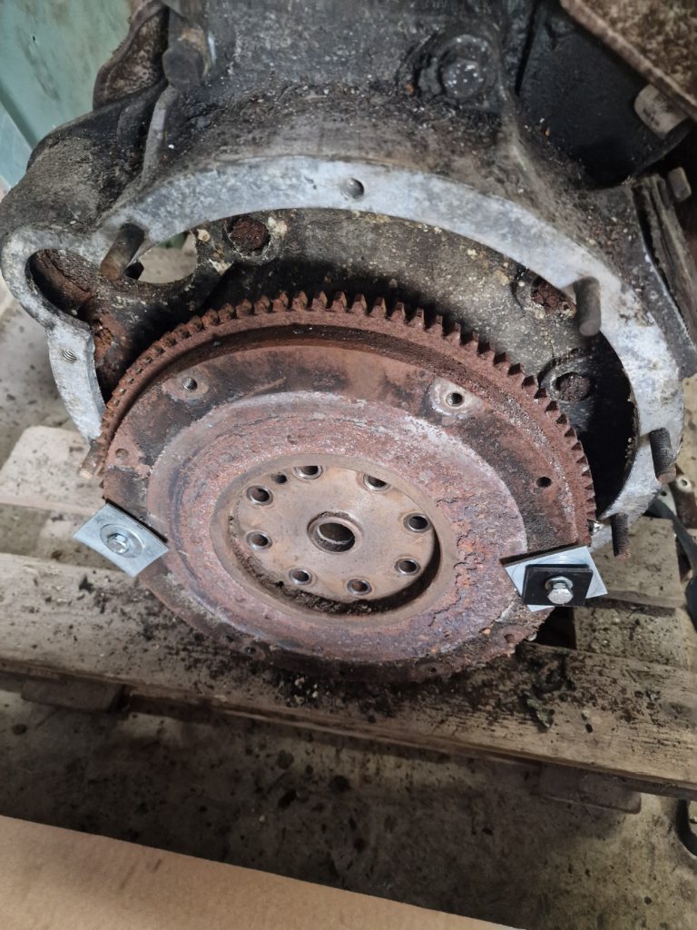
Last up was the flywheel, to me it looked beyond saving, however, this was re-skimmed back to as good as new.
Now I’m a little new to this level of detail so cant really judge the quality of work, but from what I see, the price I paid I’m super happy it all looks great and Banda, while being more used to working with people who know what the hell they are on about were super helpful.
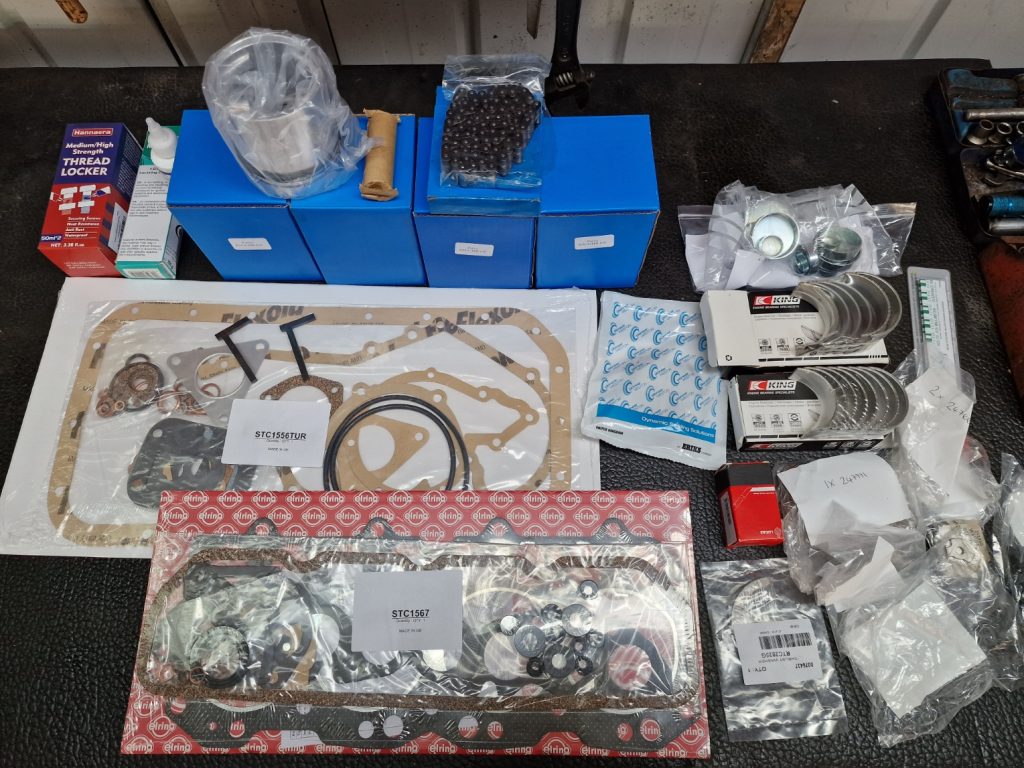
This is when things stopped for a while, except me stocking up my store cupboard with a few new parts, ready to re-start the re-build.
What did I buy? other than some Assembly lube, some other lubricants and sealers along with some more WD40, scotch bright pads and some squirty bottles.
Most of what I bought came from Turner Engineering as I didn’t want blue box (Britpart) parts In my engine, same as when I have done all other major parts so far.
Oversize Pistons (0.03)
Main bearings (Standard size)
Thrust washer for crank shaft. (Standard size)
Connecting Rod bearings (Standard Size)
Top end gasket set
Bottom end gasket set
Oil seal for rear of Crankshaft
Timing chain
Various lock tabs
All of this “should” be enough to complete the main engine rebuild.
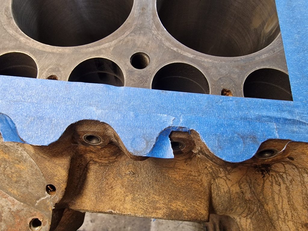
Getting ready for the build, I need to do some more cleaning, mostly ready to paint the block but also so I am working with completely clean engine parts, essential as I understand.
First thing is to mask up the block, making sure the insides keep as clean as possible and free from paint.
A little tip I saw somewhere is to put the masking take on, and then gently with a small hammer, tap the edge, which creates a really nice, clean edge.
Will come back soon, after I get the casings all cleaned up and painted and also when I start putting things back together.
Because I had not planned on doing this, well not until I knew for sure I needed too, plenty of reading and watching video’s, just so I would know what to expect. Have to say, that was time well spent.
First step was to remove the rocker cover, exposing the rocker assembly.
One of the things I did learn by reading and watching was that things need to be kept in the same place from where they came off.
Using the rocker cover upside down, keeps it all together.
Off comes the flywheel. Another tip taken from videos, was to use two bolts, a selection of washers to pull the fly wheel off. That all went pretty easily.
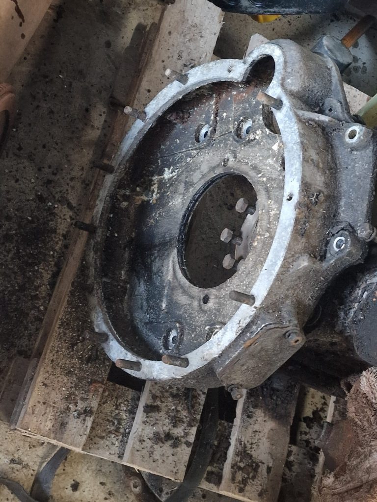
Then removed the fly wheel cover.
Then it was a case of removing all the other ancillary parts, the oil filler pipe, distributor, heater pipe tap, engine mounting brackets, oil filter assemby and various other bits.
Once all those bits were off and safely stored, next was to tackle the head. Taking care to undo the bolts a bit at a time and in exactly the right order (reverse of the order used to tighten them).
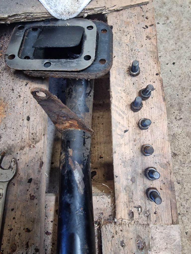
With the cylinder head off, it was time to take off the inlet and exhaust manifolds.
Humm, even me with my little knowledge knew this would not be easy, but I was surprised! the bolts started coming out fairly easily, until that is 2 snapped.
Then there was one bolt that I could not get a socket on, and could not find a spanner with grip to undo this little bugger, which had a slightly knackered head.
So, looked for a tool that would help and found these little things, sockets with a spiral inside that grip the bolt head, and small enough to fit in the gap, just.
With the help of an extension bar, out it came.
Thats it for the cylinder head for this one, will cover the rest of that in part 2 when I have bought yet another tool, to remove the valves.
Next, the timing chain. Removed the timing chain cover, which needed 4 bolts removed from the sump.
Now, the right way to do this, is to set the engine to TDC (Top Dead centre) on cylinder 1, and mark where the gears are to maintain the timing between the crank shaft and the cam shaft.
Because the engine had locked up, I couldn’t do this so will have to re-set all the timing when it goes back together.
With the timing gear off, the cam shaft can come out. To do this, all the rocker parts need to be taken out first.
Again, all these were bagged up in separate bags to keep them in order.
So, back to the main block.
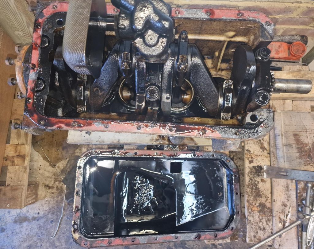
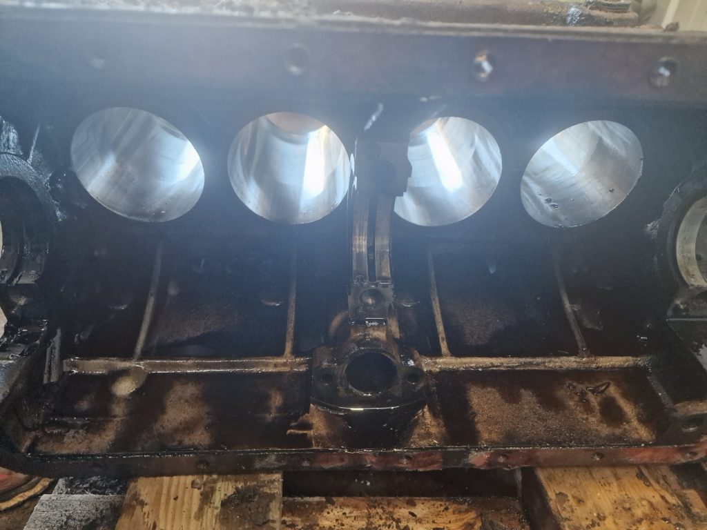
Next then, is to remove the sump, so I can get at the crank shaft, main bearings and ultimately remove the pistons.
Cant quite see it here, but in the bottom of the sump is a collection of small metal bits! Something somewhere has gone to poo!
I kind off stopped taking pictures at this point, my hands were covered in old oil, and the gloves I bought are next to useless.
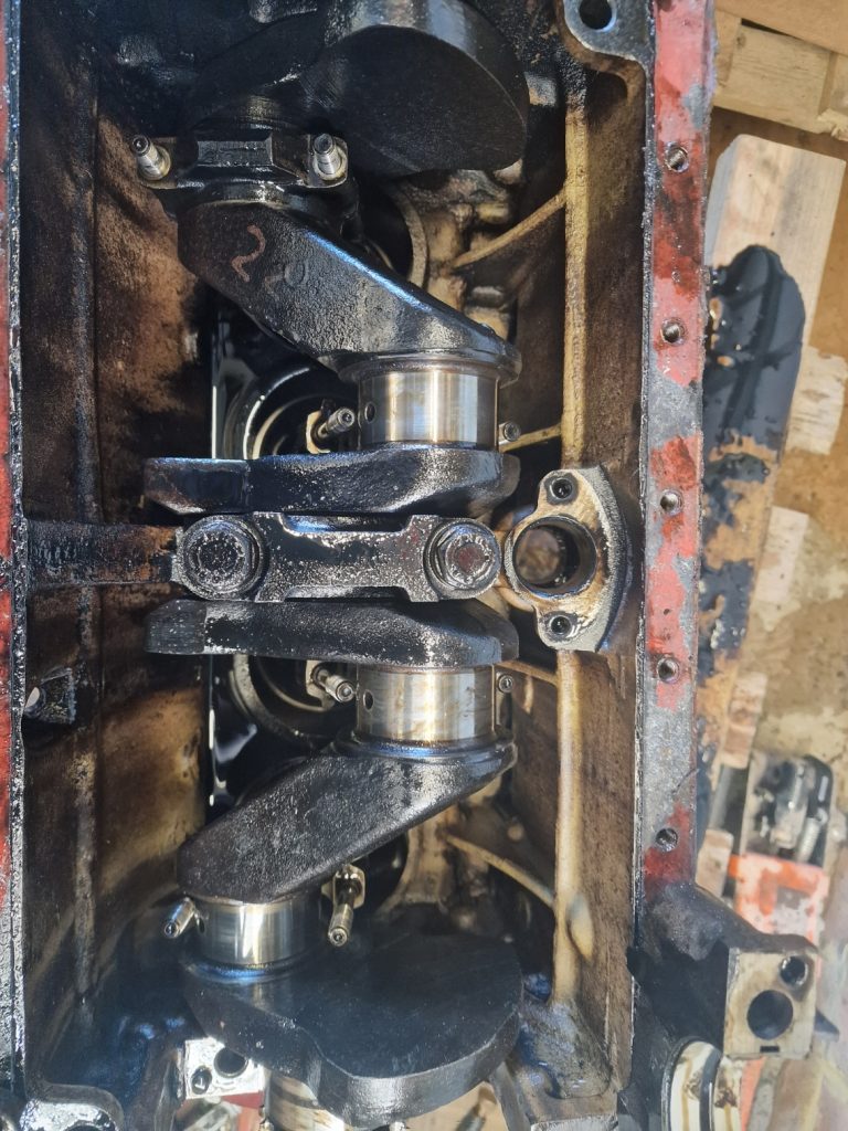
Removed the top of the piston connecting rods, keeping all of them in separate plastic bags.
This should allow the pistons to come out the top of the block.
Difficult to know how much work this engine has done, but suffice to say enough to create a small lip in the piston bores to make this a bit of a challenge.
A little cleaning with some emery cloth, and got all the pistons out eventually, except number 4, which was the one that had caused the engine to lock up.
With three out, I was able to remove the crank shaft, which gave me better access to No4, which eventually came out.
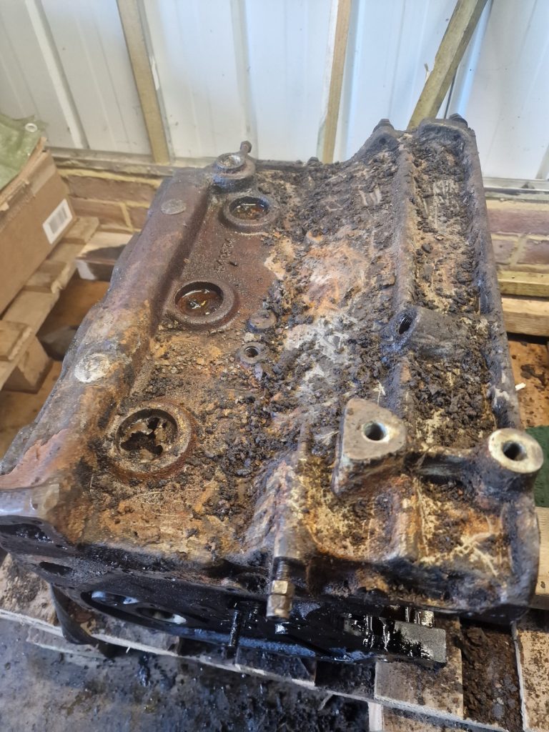
There it is, an empty block, bags and bags of bits and old Oil everywhere. Didn’t mention, before I started needed to drain the oil out, which kind of worked, until I moved the container, not realising the oil was spilling onto the floor.
To finish up, cleaned up the case a little and took out three of the casting plugs.
Will re-new these during the rebuild, after the block gets a nice, original coat of paint.
Thats it for now, will do the head next time and then focus on cleaning everything up.
This brings me to the plan, what am I going to do with it all now its in bits. Well, this is where the budget will get spent. It will be going off to an engineering company, probably in Portsmouth (based on a recommendation from my Nephew Lee) to be looked at in detail, tolerances, condition etc. and come up with a plan.
My gut feel is that at a minimum I will be looking at:
Head skimmed
High temperature valve seats in the head, to deal with modern fuels
Re-bore of cylinders or even sleeved, with new cylinders
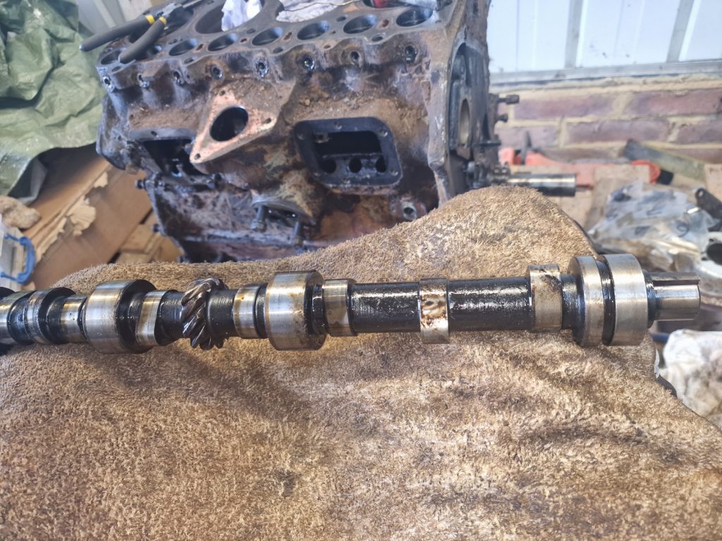
Check cam shaft and cam bearings and renew if required
Re-skim flywheel (if tolerances allow)
Remove broken studs from head
Give it all a really good clean (inside and out)
And when that, plus any other issues are dealt with, will start to put it all back together, and then get it into the chassis, along with the gearbox. Now that will be exciting.
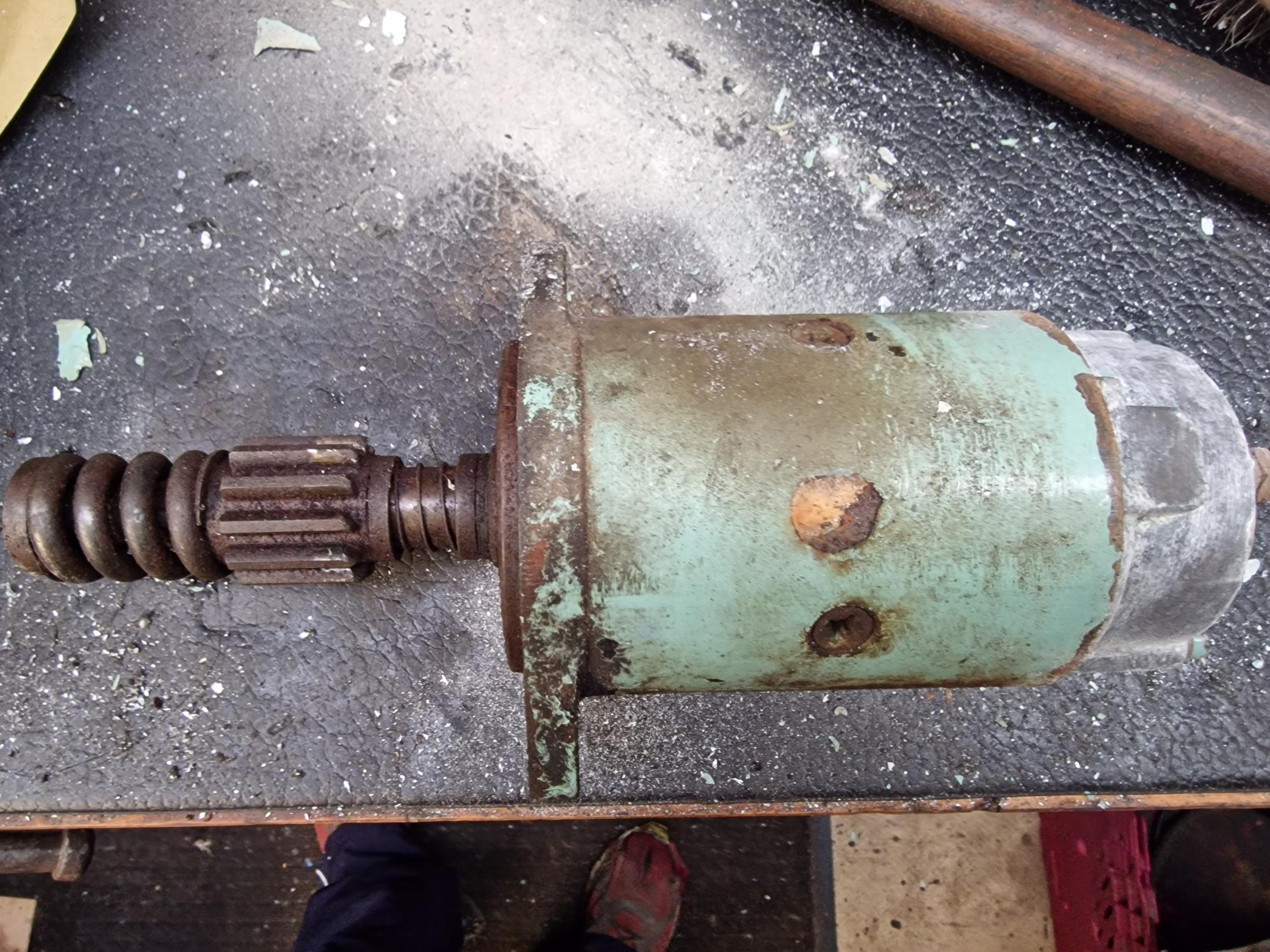
With a view to starting the engine before I did anything else to it, started to look at the starter motor.
Stripped it down into its constituant parts, which for the most part is pretty simple.
Un-screw the two long scripts from he back, gently remove the rear casing, remembering where the brushes go.
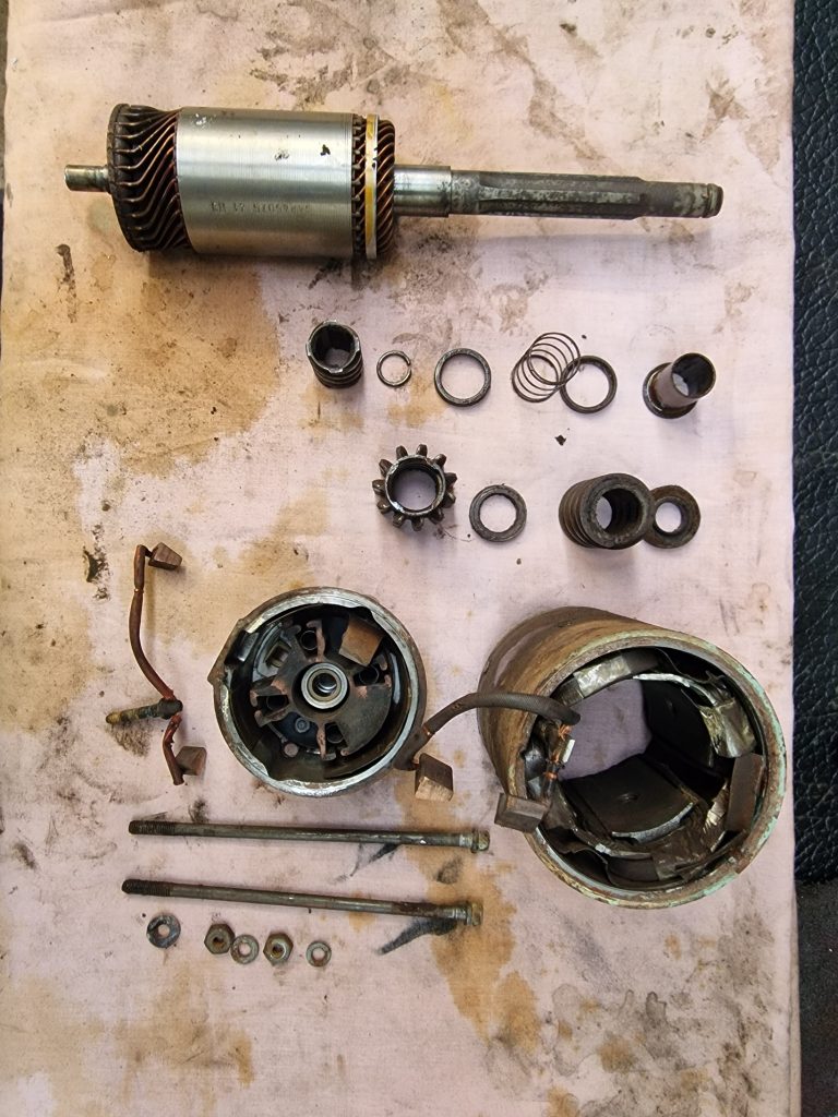
And then remove the gear from the front of the starter. The bit that engages with the flywheel when the starter motor is run.
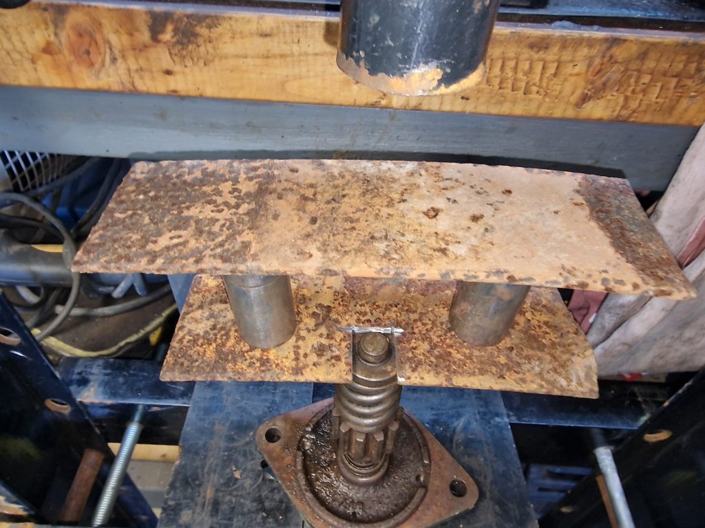
Now that is a little easier said than done. Its all held together by a small spring clip, but to get this off the big thick spring needs to be compressed.
You can, apparently get tools to do this, but I dont have one, and didn’t want to buy one.
So came up with this.
Two bits of old leaf spring, one with a cut-out, and two long sockets between them. Then, using my borrowed press, slowly compress the spring.
Now, I have to confess, I made yet another school boy error here. While cutting the leaf springs with an angle grinder, lost concentration for a moment.
My first thought was, my leg feels a tad warm! looking down I had only gone and set my trousers and jumper on fire!!! Quickly dowsed the (albeit small) fire on my leg, and all good, well nearly, ended up with a burn that was still sore a week later.
I have called this introduction, for one very important reason. I completely changed my plans for the engine, as it turns out for the good.
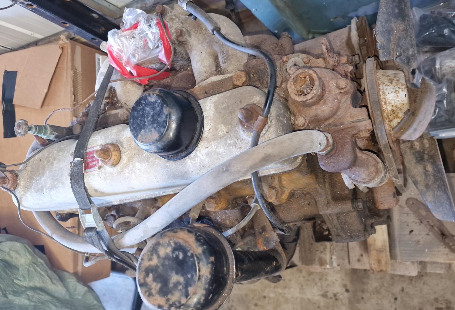
First of all, what have I got here, well, its a 2.25 litre Petrol, 3 main bearing engine, and while there is no guarantee, looking at the serial number looks like the same engine it came out of the factory with, some 59 years ago.
My plan was to get the engine running before even considering what needed to be done. First thing I wanted to do was to do a simple compression test, so bought a fairly cheap compression tester.
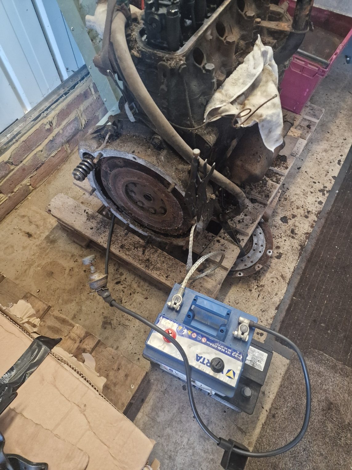
While waiting for that to arrive, I thought, lets see if it turns over on the starter motor (which I had recently re-furbished, read about that here). So connected up the battery, with the starter push button, using my new cables I bought when I bought a new wiring loom and lets see what happens.
Well, it worked, engine turned over.
BUT! after I got the compression tester, charged up the battery tried again, and….. the engine wont turn over, its locked up! SHIT! what have I done?
What I was also hoping for was to see oil on the rockers.
So, change of plan, not going to try to start it, decided I will do a complete re-build on the engine. This is going to have a massive impact on my budget and timeline. But given Isobel is highly un-likely to be on the road this year, as I had planned / hoped for, the time will not be too much of an issue, and given the amount of time and money I have spent so far, feels like it would be skimping on something so important.
So, off we go, first thing is to strip the engine down.
Been waiting a while to write up this part, mostly because I was waiting on a few parts. But here we are, finishing off the gearbox. Last time, I completed the re-build of the main gearbox and prior to that, re-assembled the front output housing and transfer box. Now its time to put them all together, and add on the handbrake mechanism and clutch assembly.
First up, connect the gearbox to the transfer case. Not much to see here, covered most of it before.
This picture is just after they were put together, and to do this had to lock up the gearbox by selecting 2 gears at the same time so I could torque up the front and rear nuts.
Oh, forgot to mention, the reason it has taken a while to get to this point, I was waiting on some new parts, one of them was the front housing seal, which I had put in the wrong way round.
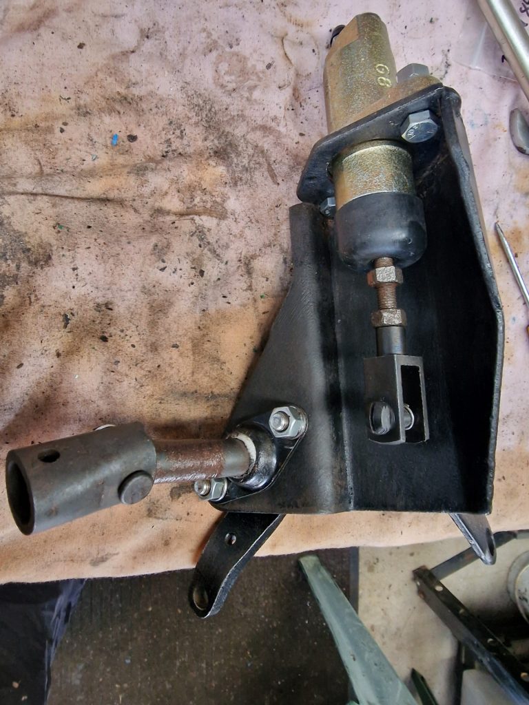
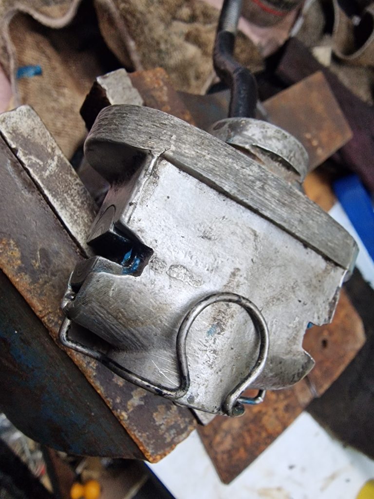
Clutch slave and assembly
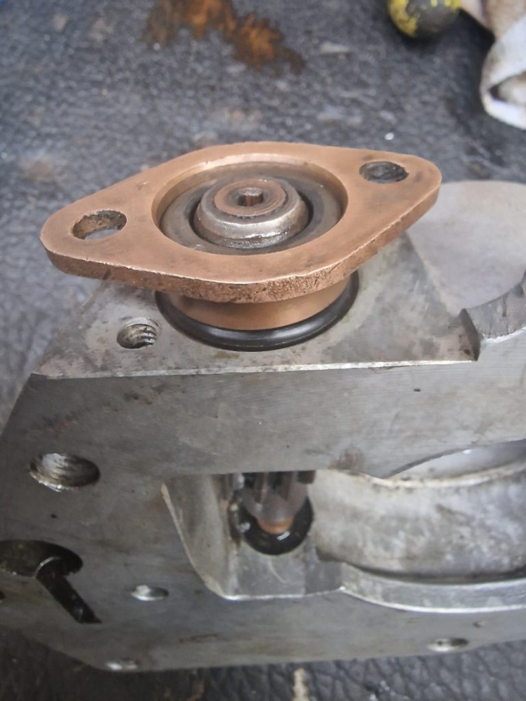
This is the support for the clutch slave cylinder.
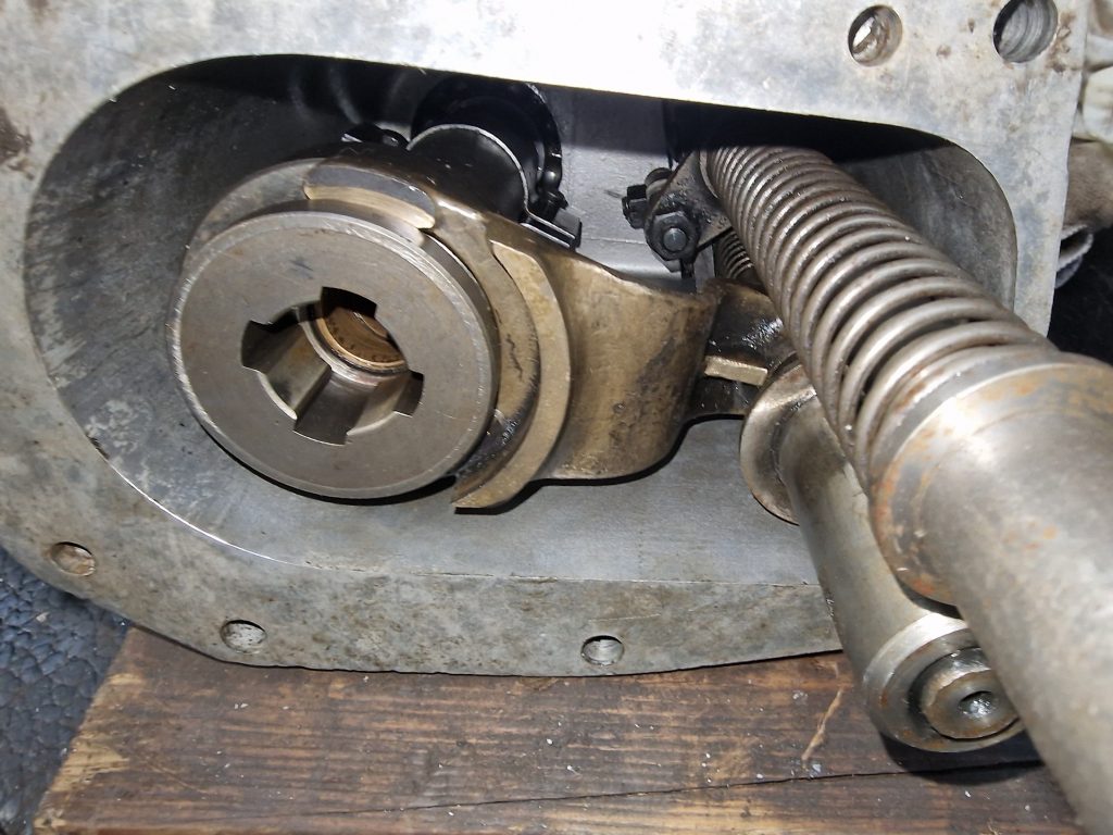
It connect to the clutch assembly in the bell housing.
Now, i’m always honest about my mistakes, and there is an obvious one in this image!
Can you see my school boy error?
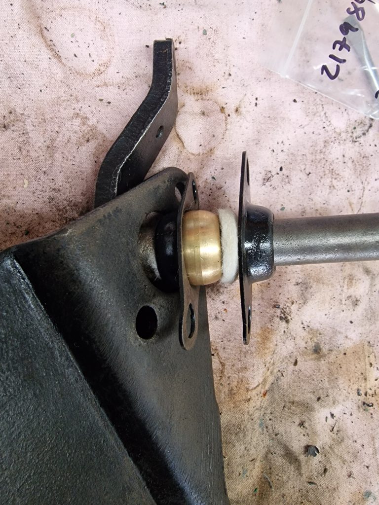
Here’s a clue to the mistake. The arm (towards the top) connects to the slave cylinder, which is shown above. When the slave cylinder is activated, it rotates the bar on the brass ball thats held in-place by the two plates which in turn, engages the clutch.
I will help you out a little, I put the arm and assembly through from the wrong side of the bracket! see, school boy error.
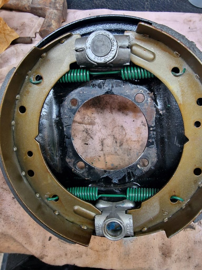
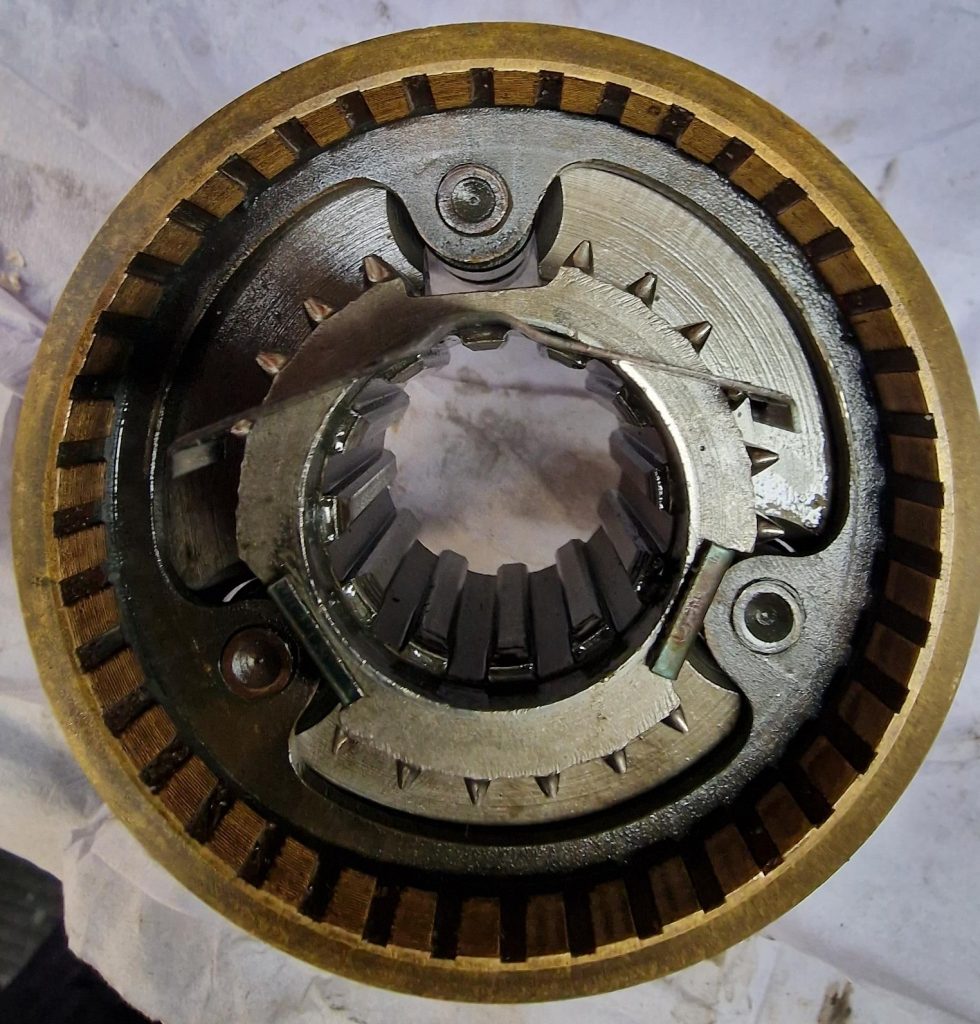
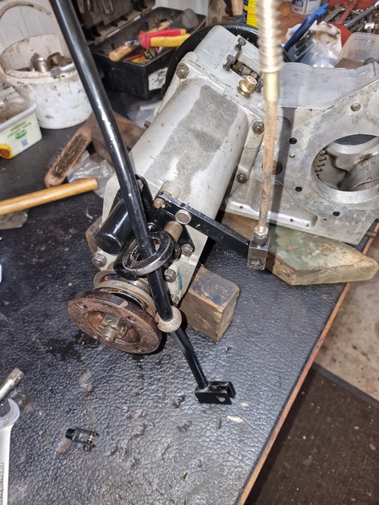
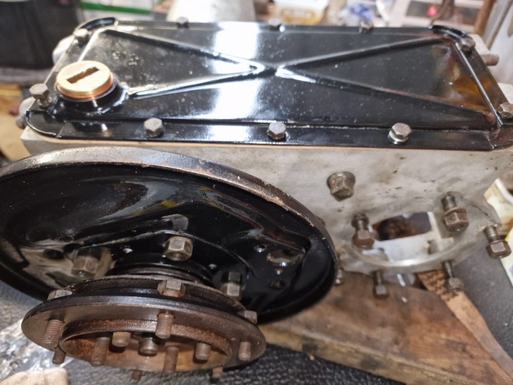
Handbrake assembly
This was a little more challenging than the clutch, even with the mistake. One of the big difference’s is that the handbrake is just mechanical, not hydraulic.
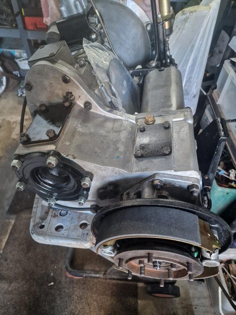
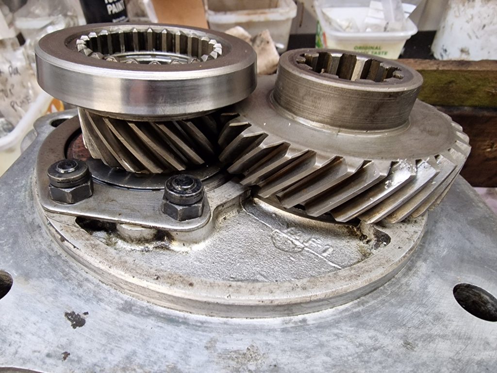
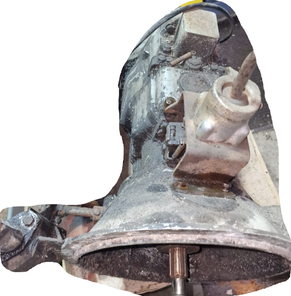
This is the finished assembly.
Basically, the two brake shoes are held in-place at the top and bottom, with two springs.
The bottom bit, is simply a brake adjuster,
The top one, is the part that is activated when you pull up the handbrake, pushing the shoes apart onto the brake drum
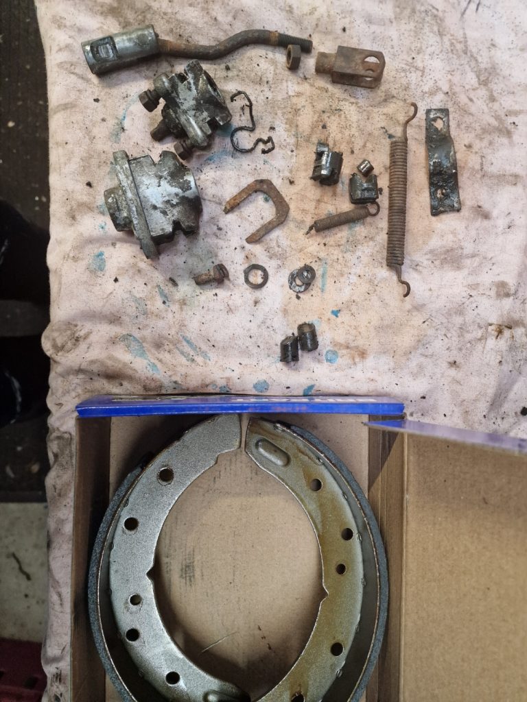
So lets look at some of these in more detail.
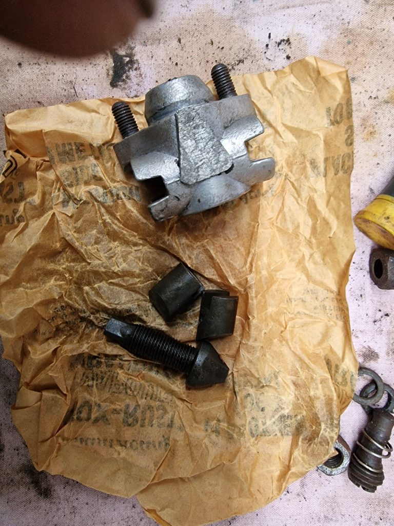
All the bits diss-ambled, with the new shoes, that were one of the first things I bought for Isobel, they were on offer!
This is the part that pushes the brake shoes apart when the brake lever is pulled on.
This is the adjuster. I renewed the 2 rollers and the adjuster.
Basically, screwing the threaded part in, pushes the sides out, hence adjusting the brake shoes.
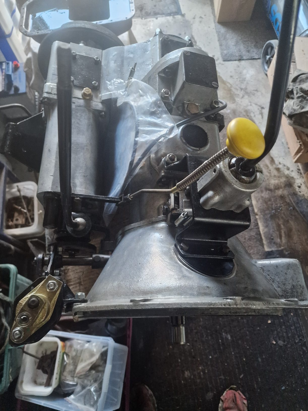
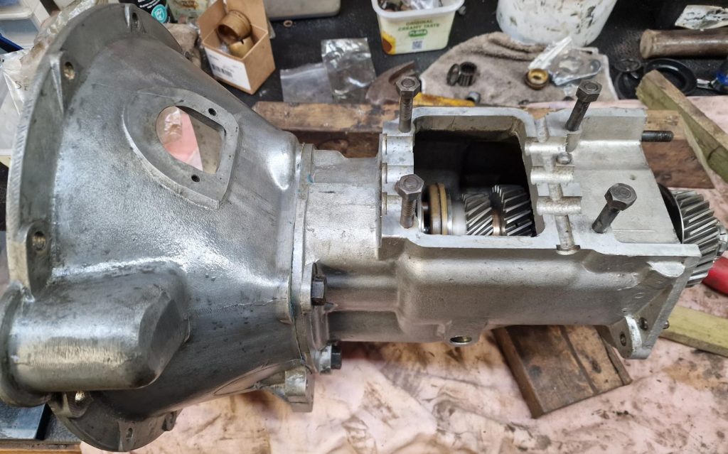
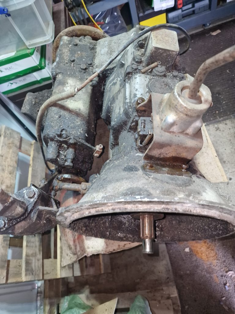
Not much else to say about these things, its all pretty simple other than what the completed gearbox looks like after these parts were added.
As with most things I do with Isobel, not totally done. I forgot to order the rubber boot for the clutch on the bell housing, and not finished painting the brake drum. Last but not least, while I can select all gears easily, low/high ranges and 2/4 wheel drive. But wont know for sure it all works properly until its attached to the engine, in the Land Rover and I try it for real.
In the last article, I stripped down and had a good look at the main gearbox, and was going to order some new parts. Well, I got the parts I needed and in this article I get to re-build a gearbox.
Before I get into the detail, cleaned up the really mucky cases, and gave them a coat of etch clear coat.
First up, the 3rd / 4th gear syncro. If you remember, one of the springs was missing, its a common issue apparently.
So ordered 3 new NOS springs (All the way from Cyprus! Not entirely sure why I did that, but I did).
Anyway, took the remaing 2 springs out, and fitted the new ones. The picture is just before I put the final one in.
I have heard from various video’s, stories of woe, putting these in, not sure why it was pretty simple.
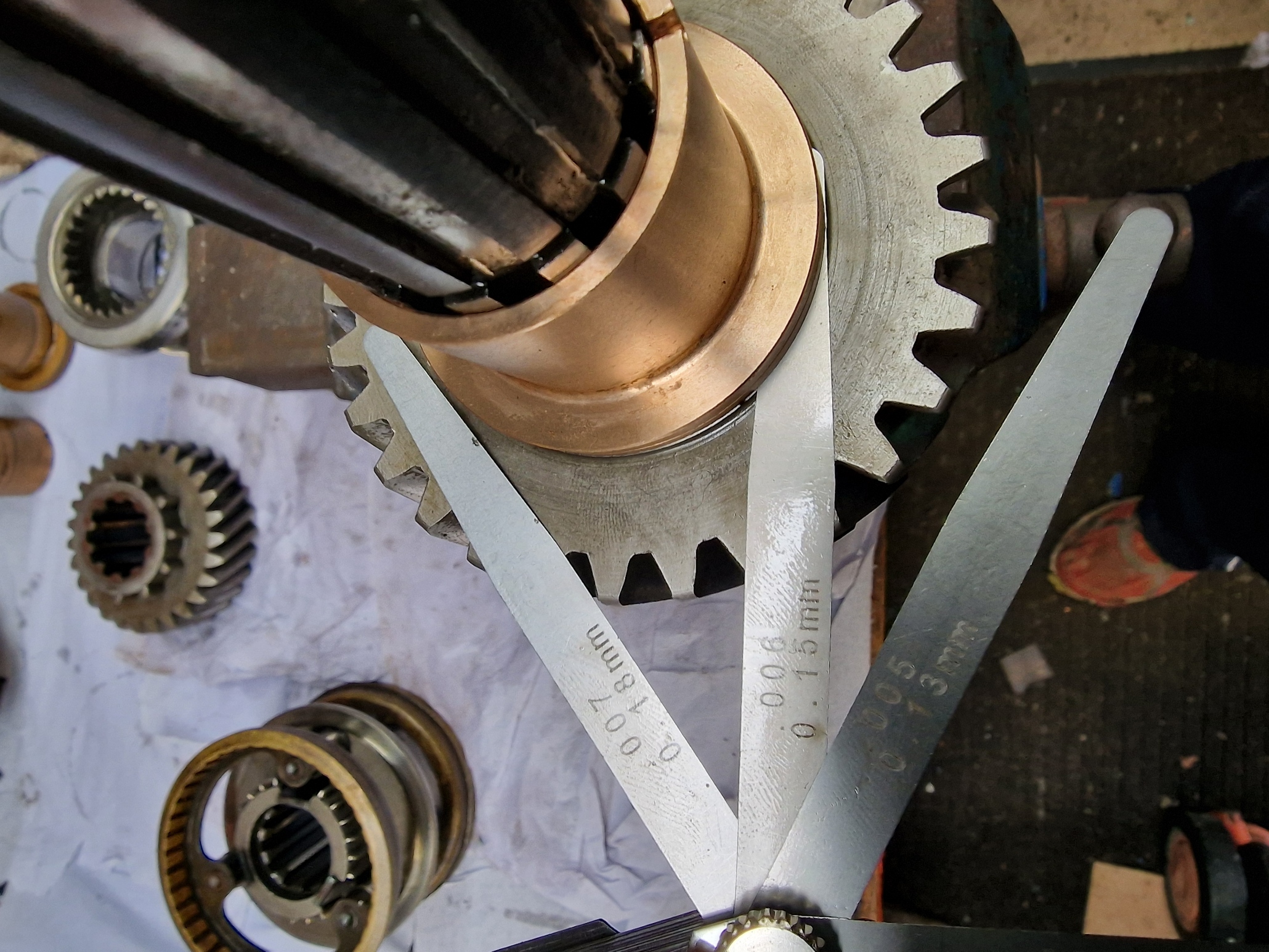
Next is the 2nd / 3rd gear bush, if you read the previous post, you will know this was broken and in 2 parts. There is an alternative to the all in one, which is to buy it already broken (actually 2 separate parts). I also got some recommendations to use the 2 part option, but, I know best, :-), so bought an OEM 1 piece part, have to say, f’ing expensive. This is the first place where there are certain parameters to meet.
2nd Gear end float3rd gear end floatBush end float
Second gear end float, between 0.004 and 0.007in is needed. It can be adjusted, but in my case didn’t need to be as it was tight on 0.006.
3rd gear end float is the same as 2nd gear, but this time the 3rd gear is inserted onto the bush.
Again, didn’t need adjusting as it came out with 0.004
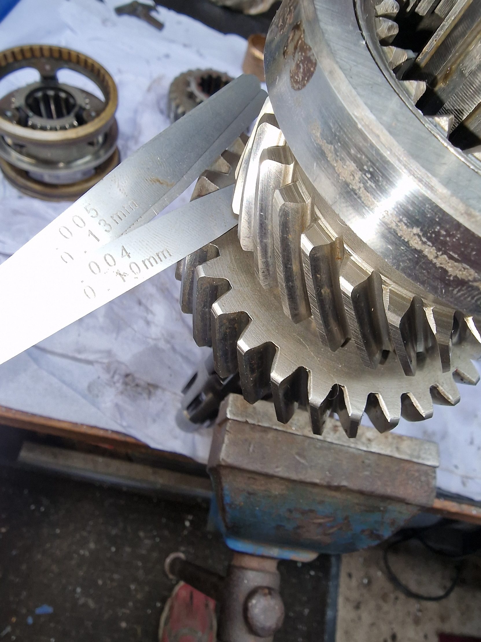
The final one is the bush end float. This needs to be 0.001 to 0.008in.
I did need to adjust this, well actually if I had read the green book, I wouldn’t have had to, by rubbing down the bush.
Ended up with 0.005in
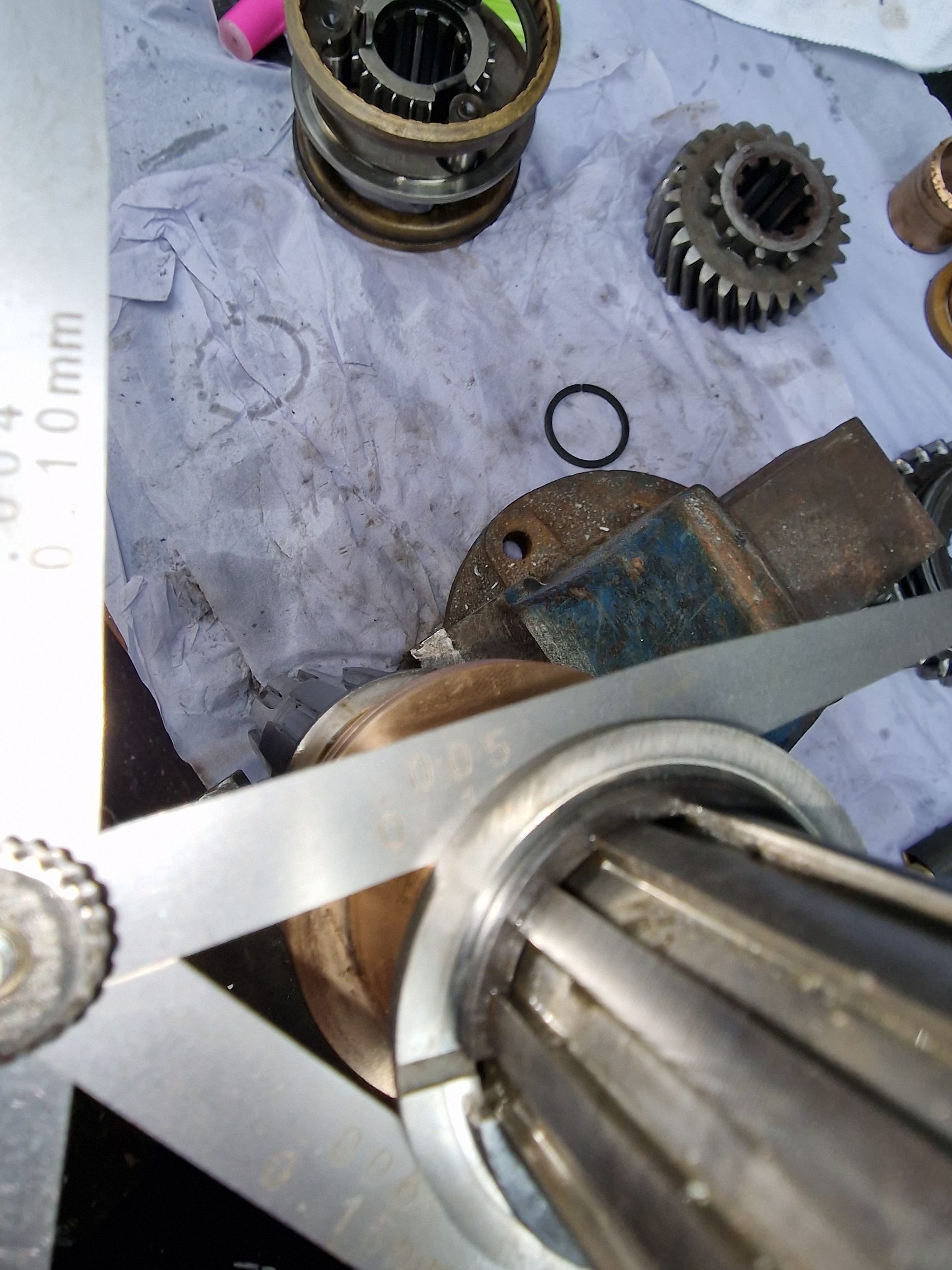
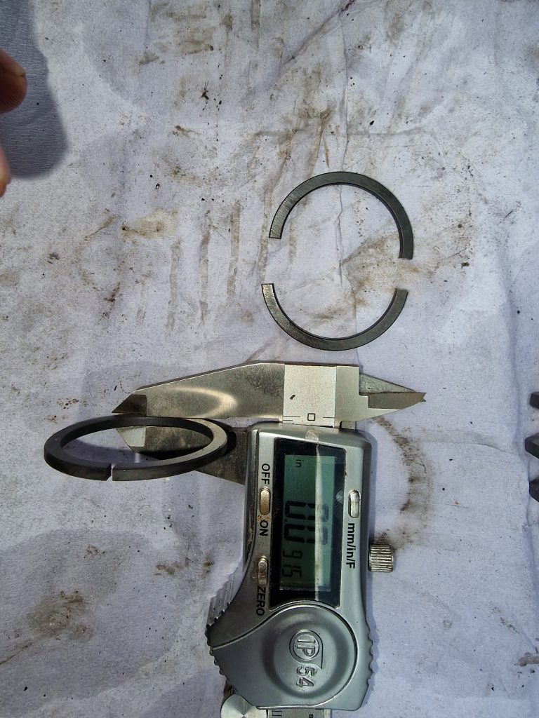
With the bush end float, a spring clip needs to be in-place. These are really difficult to get on and off. To the rescue comes the Series 2 club again. It was recommended to buy 2 clips, that are exactly the same and cut one in half, making it much easier to put on and off while setting the distance, by rubbing down the bush.
You can see above the half’s of the spring, and perhaps the reason why they are so challenging to get on and off. When everything is good, time to put the 2nd gear and 3rd gear on with the spacer washer and the complete spring clip.
Had me stumped for quite some time, until I came up with this little method, which worked surprisingly well.
Basically used split pins tie-wrapped onto the shaft, that allowed the spring clip to be tapped on over the split pins and down the shaft until home, safe and sound.
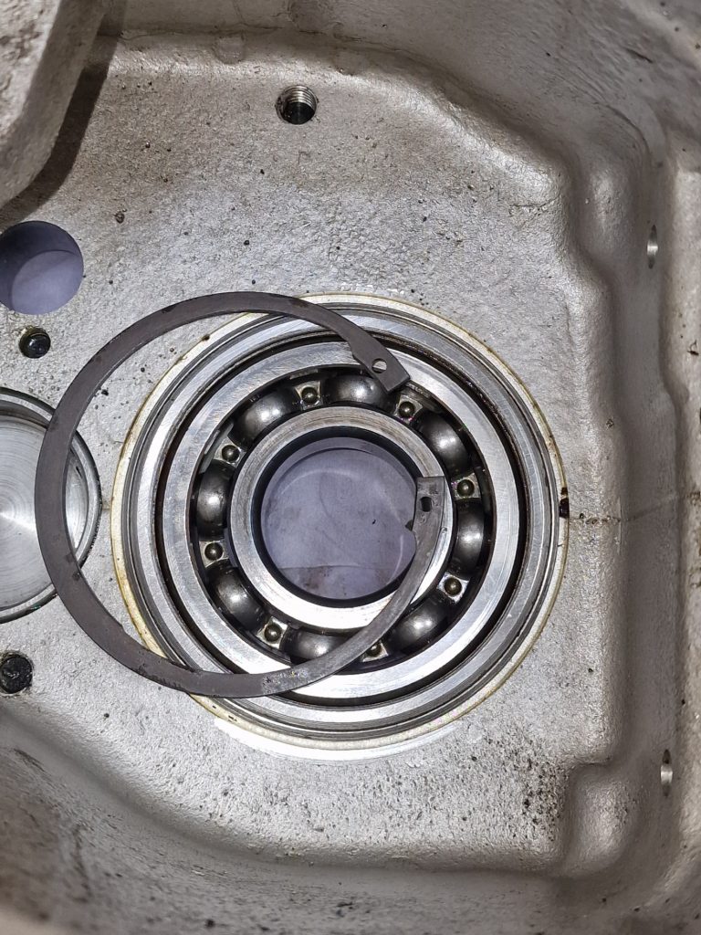
Moving on, the next job was to sort out the rear main shaft bearing and bearing housing. Now, I read my little green book and it suggested that the housing needed to be Loctite’ d on, but was contradictory to other parts of the book. Also, a couple of videos I watched, 1 used Loctite, another didn’t. So I took the housing out and ordered some Loctite, and then thought, let me ask the series 2 club again. I had one answer saying Loctite the bearing in, but not the housing, another saying not too. The chap that said not to, I bought my replacement front axle case off, and remember he said “Gearbox’s were his thing” and always gives answers to peoples questions on the forum, so went with that. that did mean of course, I had to put it all back in.
Inside the housing, a circlip needs to be inserted to hold the bearing in-place. When I took the whole housing out, I realised (and the green book says) its much easier to do out of the case, than when its still in the case.
Ignore the gear and the oil thrower and you can just see the circlip on the housing, that holds the housing in the right place.
Out of intertest, this circlip is huge, and pushed my little circlip plyers to their limits.
Finally, the main shaft was pressed into the bearing. Again, recommendation was to press it in, rather than brute force, so my borrowed press came in useful yet again.
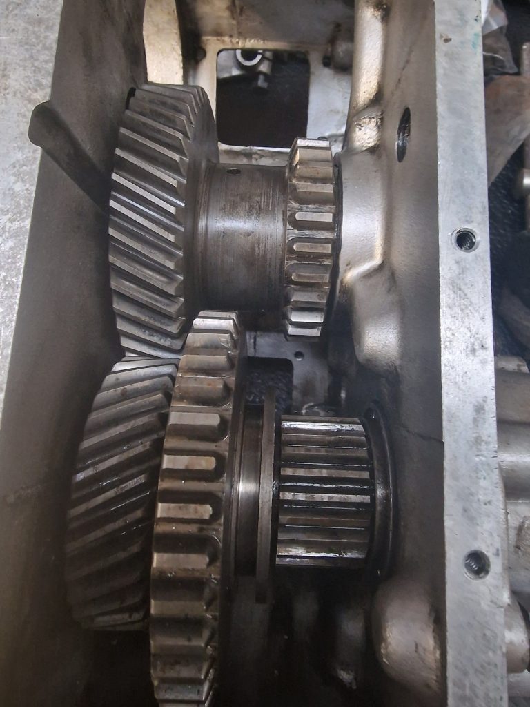
Probably worth a look at the main shaft at this point, so here it is, with all the gears, syncro and oil thrower in-place.
Actually, before I pressed the main shaft in, I put the reverse gear mechanism and gears in. This required a little more brute force than I would have liked, as the shaft, needs pressing in from the back of the case, and it was tight.
A little bit of heat, and a large hammer got it home without any collateral damage.
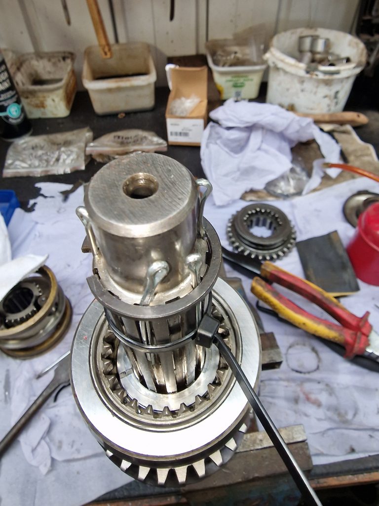
Now the main shaft is in, as is the reverse gear, time to add the lay-shaft. I got it in, after figuring out how too, and tried the bell housing on (Pics of that further down) As with all things, had me stumped for a while. The bell housing would not sit properly, turns out I had put a little roller bearing, that is in the back of the box in the wrong way around!
The Lay-shaft sites in a roller bearing at the bottom, and with a little fiddling, moving gears around, finally got it in.
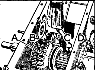
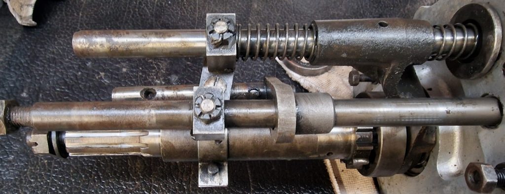
The Layshaft is the shaft at the top in this picture.
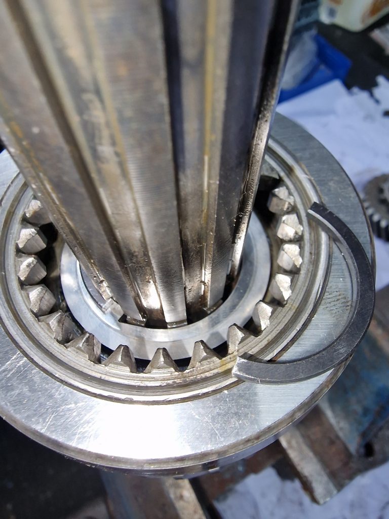
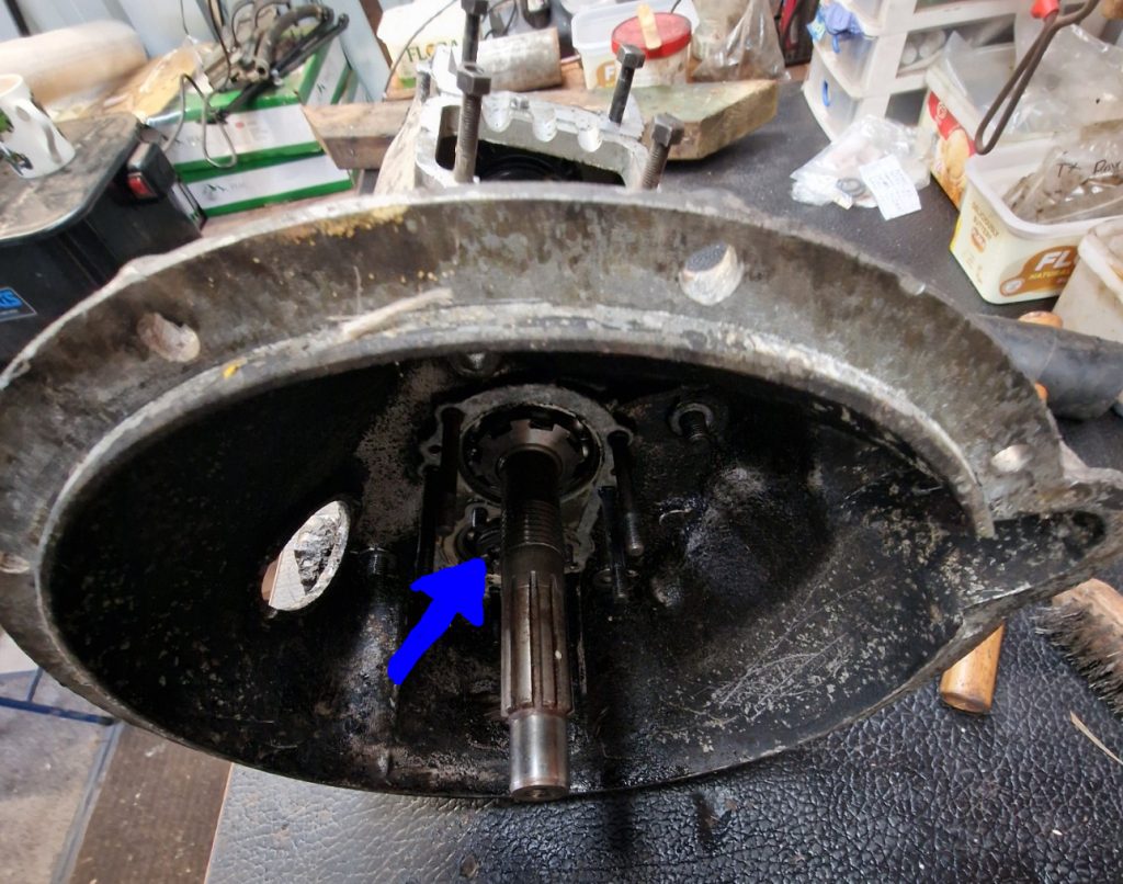
The last part is to put the bell housing on. Again, watched endless hours of videos of people doing this, and almost without exception, everyone said this is really tricky. Why?
Well, this is the back of the bell housing, already added the gear on the left (Primary pinion), which the main shaft needs to be located in, and the gear on the right (Constant gear) with a spacer underneath needs to go over the lay shaft. But as you can see, its not attached, and needs to sit behind the primary pinion gear.
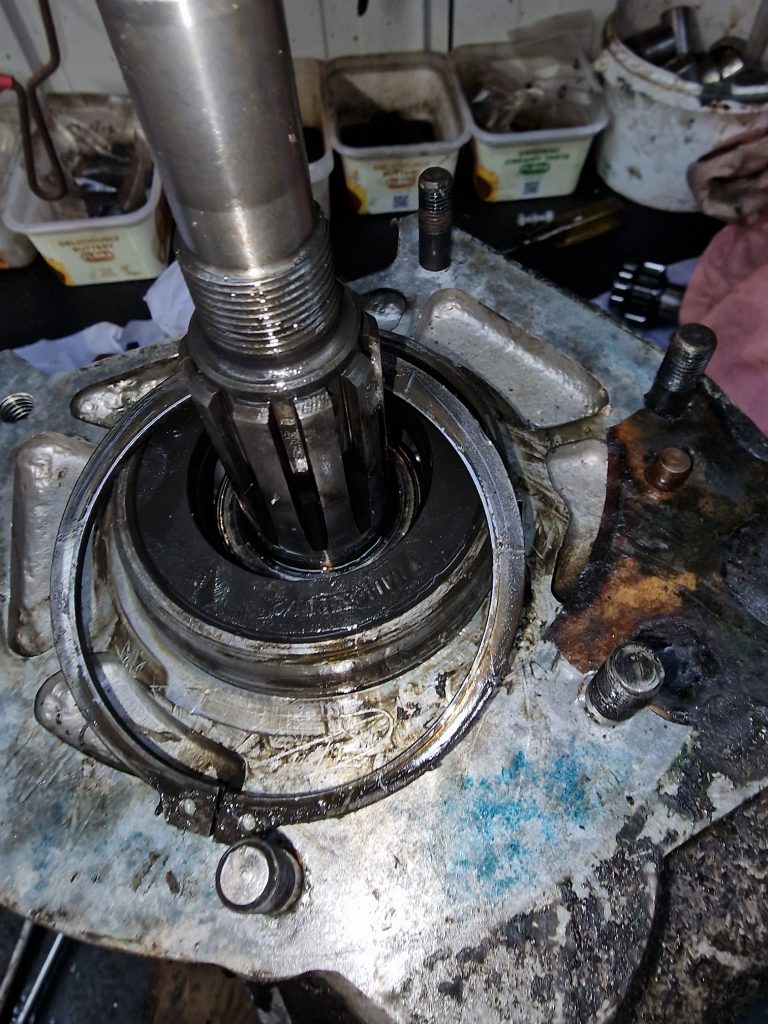
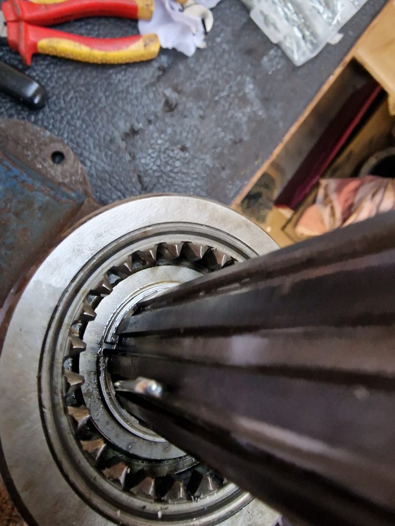
For context, these are the two shafts the above needs to be located on. (top being the lay shaft, bottom being the main shaft).
Anyway, the little green book (500 ish pages) says to locate the gears as I have them above, and holding them in position with fingers through the bearing, position the bell housing onto the gearbox main case.
I have to say, with a tiny amount of jiggling around, it all went pretty smoothly. So, the moral of the story, dont believe everything you read or listen to on the Internet, use your brain, think and importantly “RTFM”.
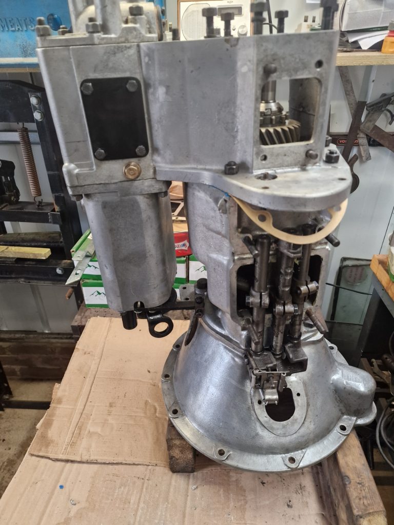
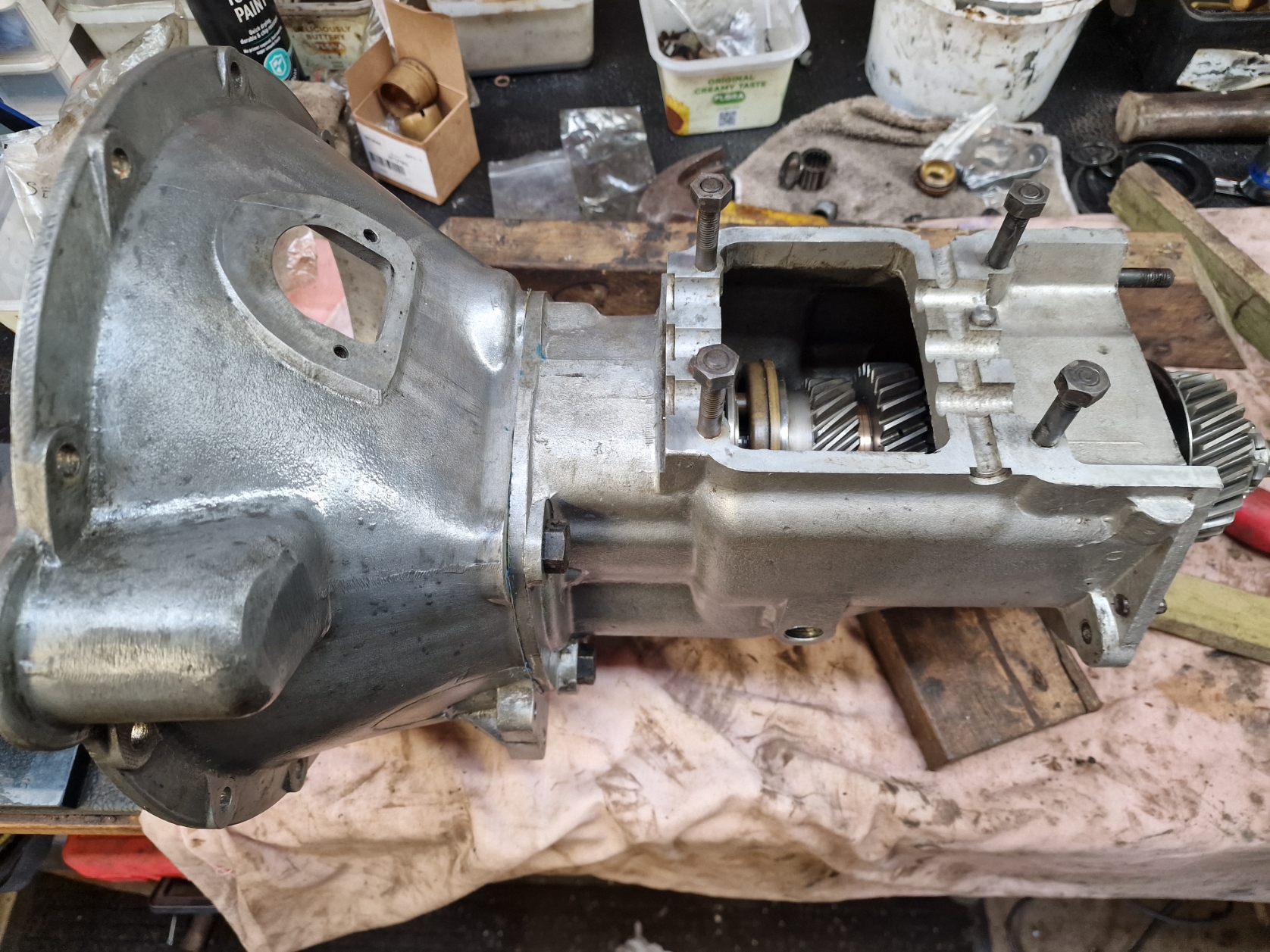
So here it is, the main casing with the Bell-housing attached and all the gears, hopefully in the right place.
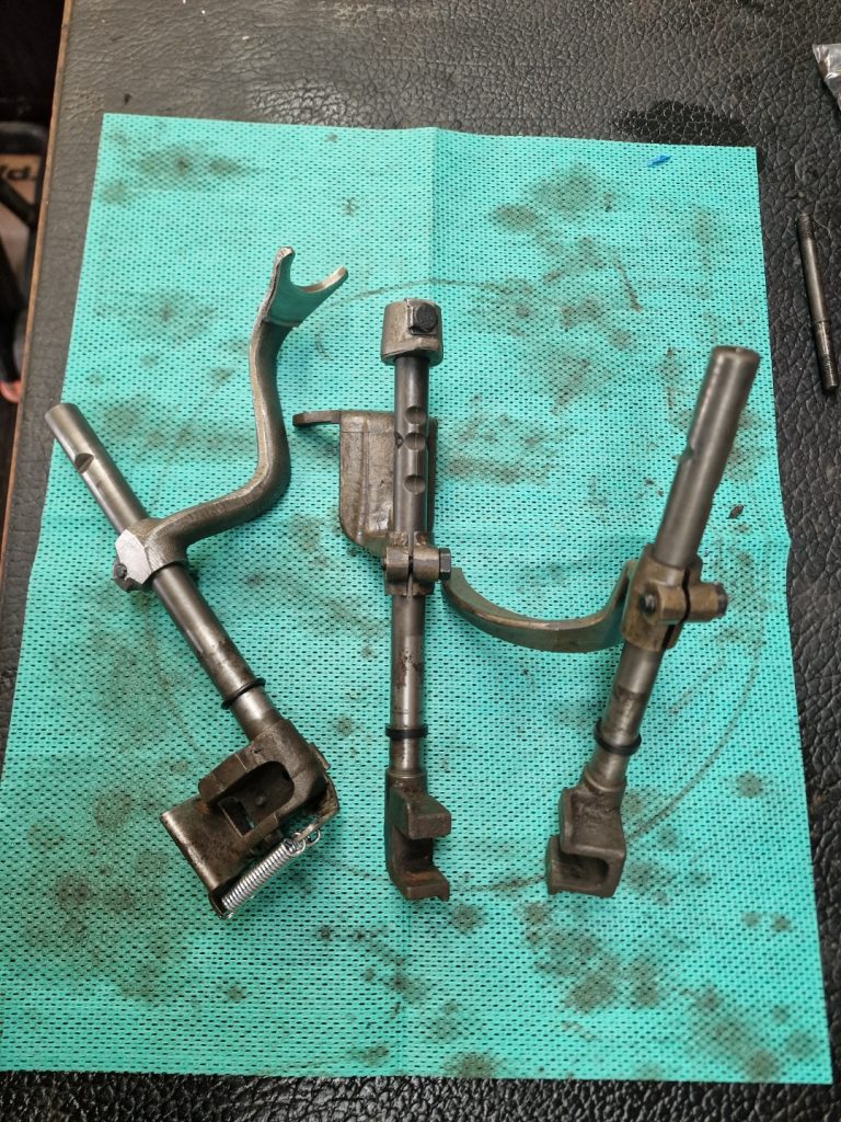
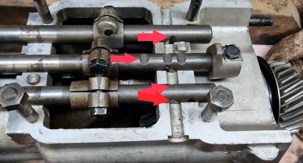
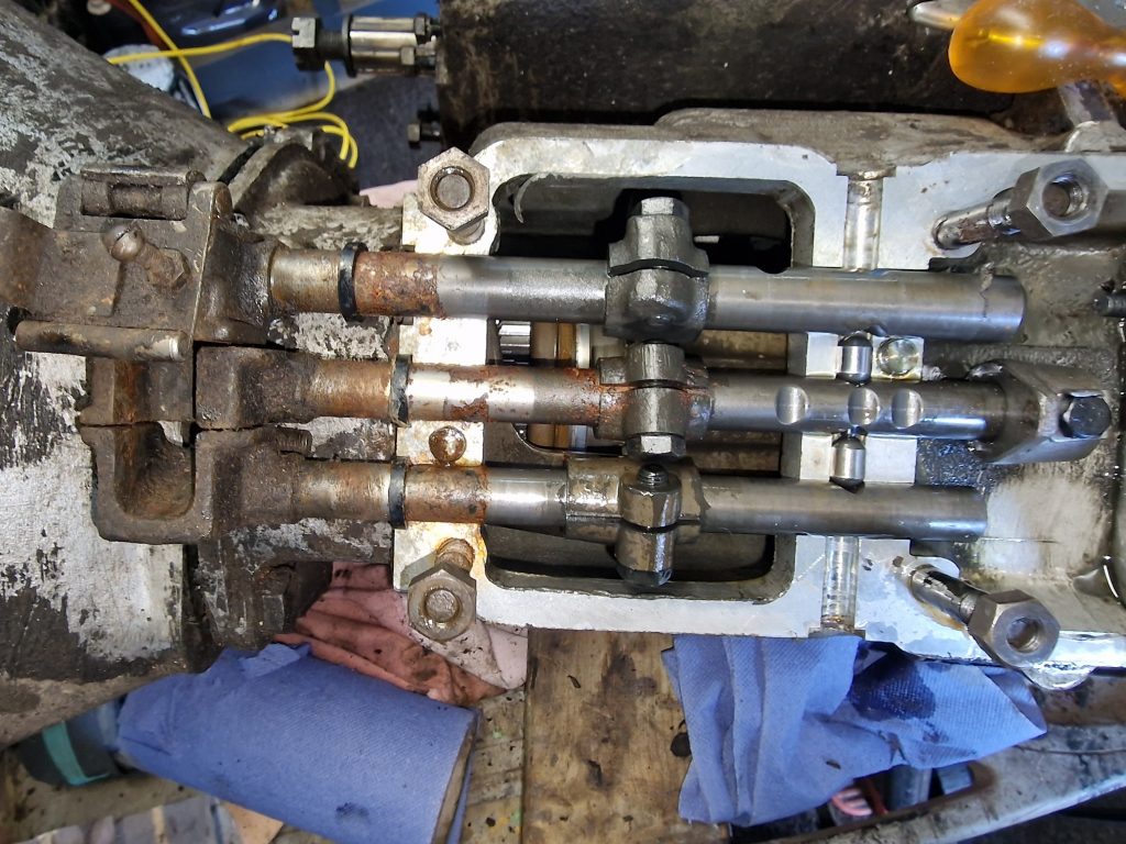
The selector forks need to be inserted, in a specific order. (3rd/4th, 1st/2nd and finally reverse).
Its at this point, I got excited about progress, and forgot to take more pictures, so here’s what they looked like before I cleaned them all up.
From the left, reverse gear selector, 1st/2nd gear selector and finally 3rd/4th selector.
Again, dont believe everything you hear on the Internet, everyone says how tricky it is to get them back in and make sure they are located properly. A little more jiggling, and they were all good.
With the selectors in, I can make sure it all works.
So here it is, selecting gears and “seemingly” working.
I should have stopped at this point, because I need to tighten up the shaft bolts, and that requires the gearbox to be locked up, typically by selecting 2 gears at the same time. You cant do this, for obvious reasons normally, and this is achieved with the next parts I put on. But put them on anyway.
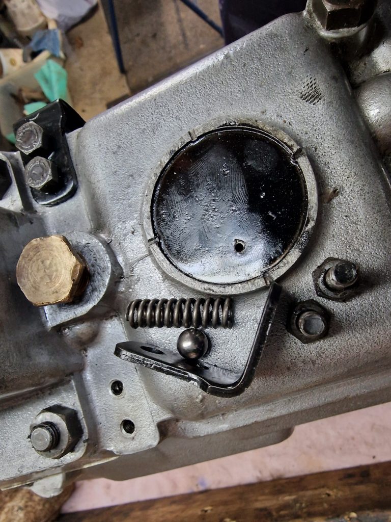
Put the top case on over the selector shafts, and added a series of ball bearings held in with springs.
These stop 2 gears being selected at the same time, by locating in the little grooves on the selector shafts.
One of them is fitted (image to the left) and one ready to be fitted (less a small rubber seal).
There is two oval balls that sit between the shafts, two round ones that are in the sides of case and there should be one in the top, but I couldn’t find the ball bearing to go in there. Nearly bought one for £0.74 + £5.95 shipping, but checked the part number, and its the same as the ball bearings in the steering box, which I replaced, so somewhere in the workshop, I have the old bearings. I haven’t thrown anything I have replaced out yet, so they are there somewhere.
Thats it for now, few things to finish up, add the clutch housing, find that ball bearing and tighten up the shaft nuts, and lastly, put the transfer case (done previously) and this part together to complete the gearbox.
So, until next time, hopefully next weekend, bye for now.
After stripping and re-building the Transfer Box and Front Output Housing with all the bits and bobs in those, I started to strip down the main part of the gearbox. I have to say with some trepidation, as I have never done this before, and whenever I mentioned to people I was going to do it myself, there were always plenty of, “are you sure, its not easy, gearboxes are very complicated”.
Well as it turns out, its not that difficult after all, well the strip down anyway, the re-build might be a bit more challenging as there are a few tolerances to be aware of and make sure are set correctly.
the real purpose of stripping it down, similarly to the Transfer and Front Output housing was simply to check it all out, replace any parts that had obviously worn out, change seals, gaskets etc. so nothing major.
This is the part I’m interested in, the other parts are the transfer box and front output housing.
First thing (actually I had already done this, before I did the Transfer and Output housing) is to remove the Selector rods. From top to bottom, we have the Reverse Selector, 1st and 2nd gear selector and finally the 3rd and 4th selector rods.
They are a bit awkward to get out, but a bit of jiggling and out they come.
I didn’t take many pictures of the actual strip down, sorry for that.
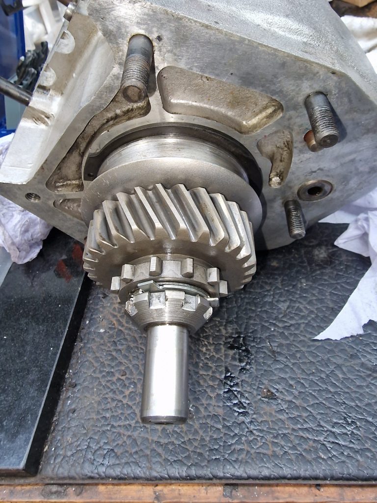
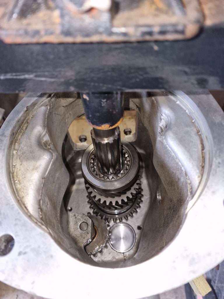
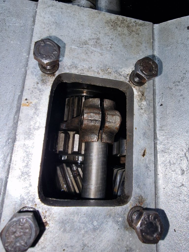
Other than a couple of plates on the back of the box, this is the first bit to come off, its a castle nut, that should tightened to about 85ft lb. Trouble is, I couldn’t find a socket to fit (no idea what size it is), so resorted to a screwdriver through the case hole (on the left) and knocked it loose with tool No# 1. (Hammer)
This releases the Bell housing from the main gearbox case, but also allows the Layshaft to come out, and some of the gears off the main shaft, leaving behind the main shaft and the reverse gear.
This is the top of the main shaft, which needs to be knocked out, with, I have to say took some force, but it did come out.
There is also a rather large circlip holding the bearing housing in-place, which caused me no end of frustration… I’ve only got relatively small circlip plyers, and this was a bit of a struggle.
Also took out the seal, and the bearing sat underneath it.
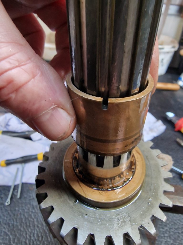
The next challenge was taking off the 2nd and 3rd gear off the main shaft.
You can just about see a split washer holding the gear in position on the main shaft.
I dont have a tool to remove these, but thanks to one of the many videos online, learnt a little trick, which is to lever the washer apart, and slide in split pins to hold it. Then gently, it can be slid up the shaft, releasing the gears, and importantly a bronze bush.
It was this bronze bush I really wanted to see, as they are apparently susceptible to breaking.
Finally, had to punch out the reverse gear and shaft, which needed the casing to be warmed up and the shaft driven out. (sorry, no pics of that at all).
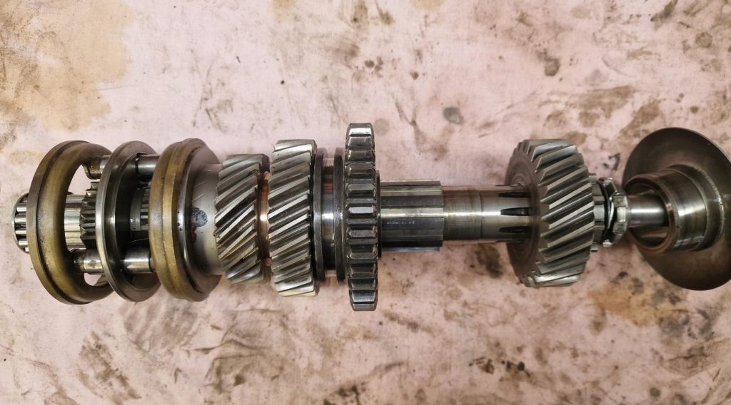
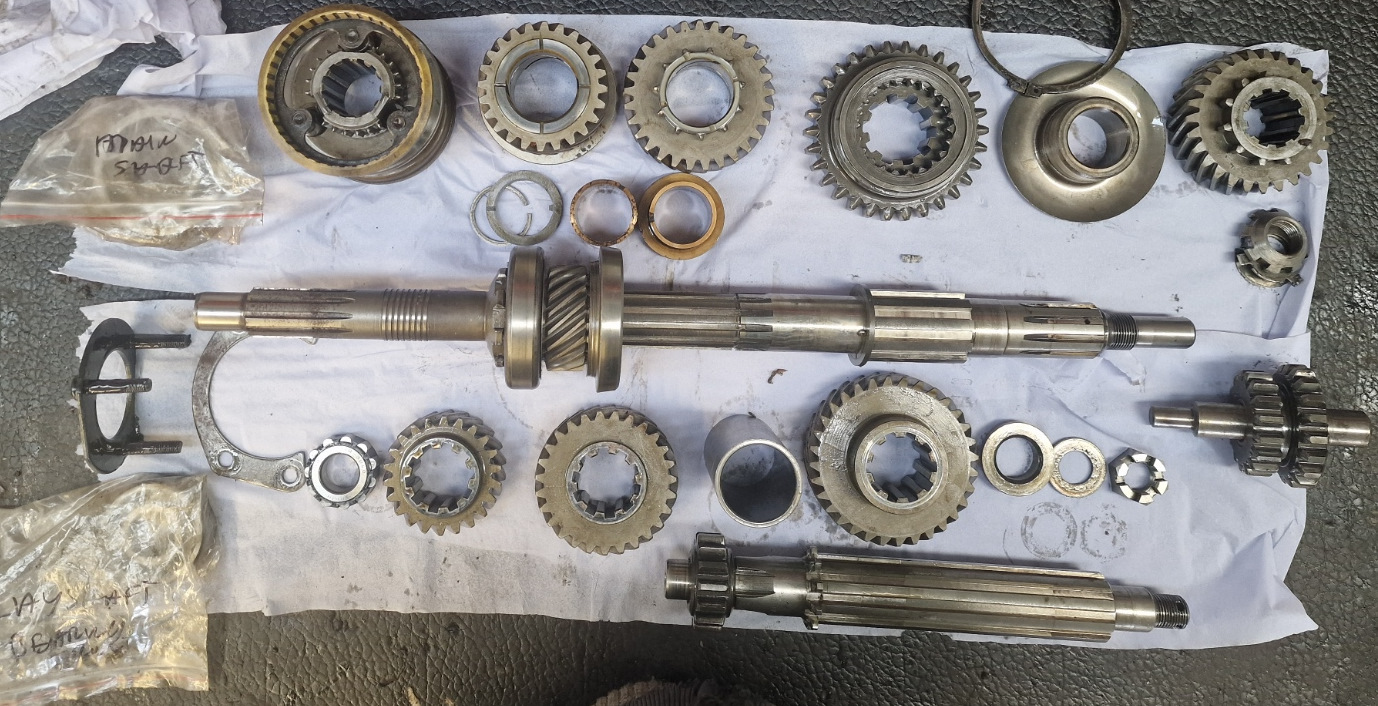
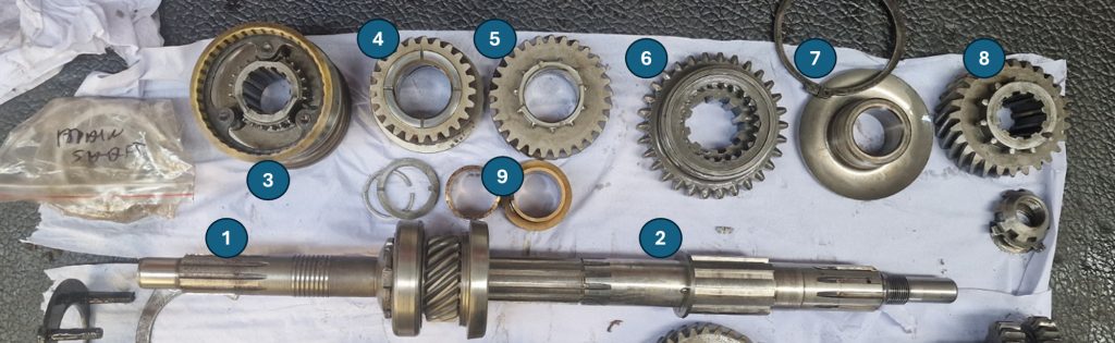
So what am I left with, well, a nice collection of gears, spacers, shims, bushes and shafts. So here goes, my attempt at an explanation of all the bits.
This is the main shaft, this is the shaft that holds all the driving gears, and its the moving of thsese around that selects the various gears (except reverse).
Front half of Main shaft (Primary Pinion and constant gear)
Rear half of main shaft
3rd / 4th gear synchromesh
3rd Gear
2nd Gear
1st Gear
Oil Thrower
Main shaft gear for transfer box
4th Gear, because it is selected by the Syncro, I “think” it is the gear on the primary pinion and constant gear, locking the main shaft and primary pinion together, to give drive.
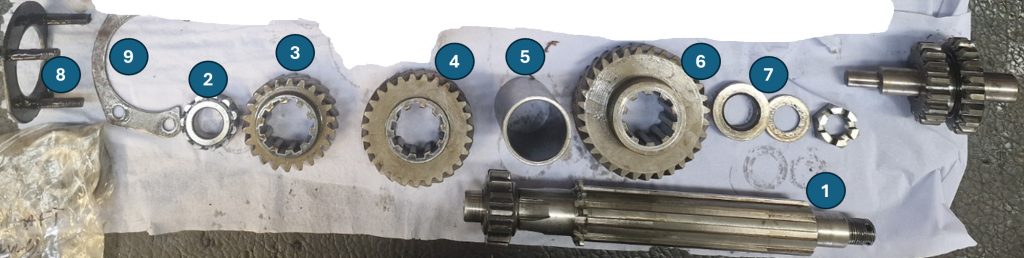
The Layshaft sits along side the main shaft.
Layshaft
Roller bearing
Constant gear (layshaft)
3rd gear (Layshaft)
Layshaft sleeve
2nd gear (layshaft)
Roller bearing
bearing plate
Retaining plate
The part top right, that is not numbered is the reverse gear and shaft.
Starting to wish I’d never started to write this part up.
A much better explanation can be found here. Its a video that explains things much better.
The gearbox in that video is not the same as mine, its a later version which has Synchromesh between 1st/2nd and 3rd/4th. Mine, only has Synchro on 3rd and 4th. (Old school between 1st and 2nd, double the clutch when changing)
OK, so I have it all in bits, what next. Well, the first thing I did was post some pictures on the Series2Club forum, with the question…. Are these OK or scrap? I asked because I just dont know, as I have nothing to compare with.
The answers came flooding back, and happily, the consensus was that while I could replace a few bits, generally it all looks OK, so long as I’m not planning on doing the Dakar Rally any time soon.
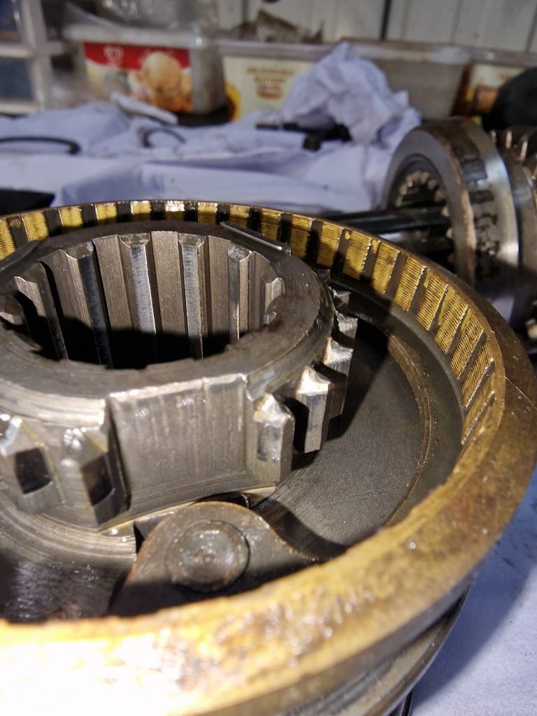
That said, there are a couple of things to look at. 1. The Syncromesh has three. well should have 3 springs that keeps the central part central as it moves between 3rd and 4th gear. One was missing, quite common apparently.
The second issue was that the Bronze bush that is a common point of failure, had actually failed so that needs replacing also.
Final part, for completeness is the clutch housing and mechanism. Not taken this apart just yet, might leave as is, need to look and see if it could do with any new parts.
So thats the Gearbox stripped down, all I need to do now is to clean it all up, casings, gears, shafts etc. order some new parts, and put them all back together. Thats where I need to take my time, make sure all the tolerances are set accurately. Had some really good advice on this also from the Series2Club forum.
I did consider replaces one of the gears that is showing a little more wear than the others, and the bearings, but the consensus was that what I have will likely be perfectly ok, and I wont really know for sure until the gearbox is being used. So it will go back together with what I have and see how it performs when I get the drive Isobel for the first time! If its not right, we’ll it will simply have to come back out and re-built again, but this time knowing what to focus on and what actually does need replacing, if anything.
The last time I was stripping down the gearbox, more specifically the Transfer Case and Front Output Shaft housing. I was faced with a snapped bolt that is supposed to hold the 4WD lever.
I mentioned what I would try, which was to try a bolt extractor, which I did, and which didn’t work, it made no impact on the bolt all.
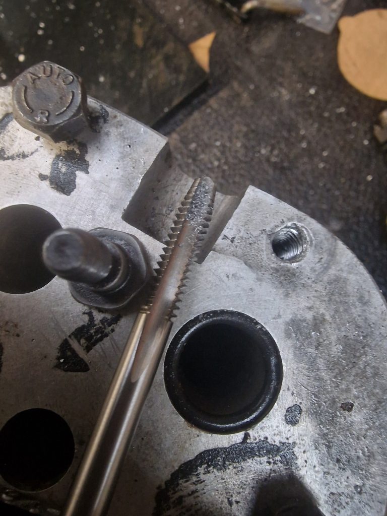
Next option was to drill the old bolt out and re-tap it. By this time I had the new bolt which just happened to have 1/4″ Whitworth thread. Oh crap, another new tool needed.
Anyway, the upshot is, that by carefully drilling out the old, and re-tapping the hole until the new bolt went all the way home, It is now sorted.
Before starting to put things together, bit of evening work to clean up some parts and get them painted.
Onto the re-assembly. the first thing to address is the Speedo housing.
The Speedo housing is pretty simple, cleaned it all up, fitted a new ‘O’ and put it all together.
The speedo housing needs to be fitted to the Transfer case before anything else, as this sets the pre-load on the Output shaft. To set this, according to the green bible you put the speedo housing on, without any shims (see pics below) and gently tighten, until the pre-load is set to between 2 and 4 ft lb
These two pictures show the shims that sit between the speedo housing and the transfer case, and the method for measuring the pre-load. (I thought I had taken a picture of this, but seems I didn’t).
On the left, these are the shims.
Because I didn’t change any bearings, I assumed it would be good with the same number of shims. Not the case, had almost no resistance.
Adjusted the shims by removing one, which gave me the correct readings.
The method (from the green bible). Basically you wrap a cord around the Low/High selector wheel and pull it with a fish scale.
On this, the green bible says to wrap the cord around the selector, however when I watched various videos on how to do this, they wrapped the cord around the smaller gear. I ended up with just over 2lb ft around the selector, and just below 4 lb ft on the small gear, so as far as I can tell, all good.
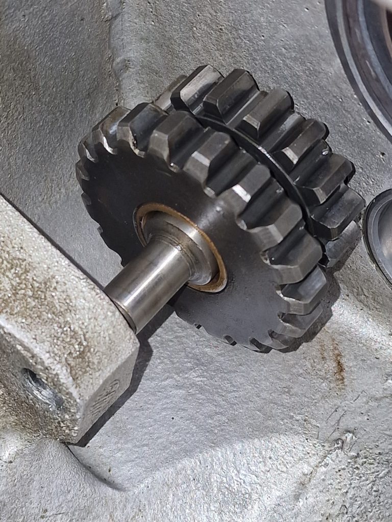
I then, although I didn’t need to, put the intermediate gear back in. There is also a measurement to be taken here also.
I probably should have remembered to put the Low/High selector in before I did this, so had to take it back out to get the selector in.
This is the selector in the right place, ready for the selector shafts to be inserted.
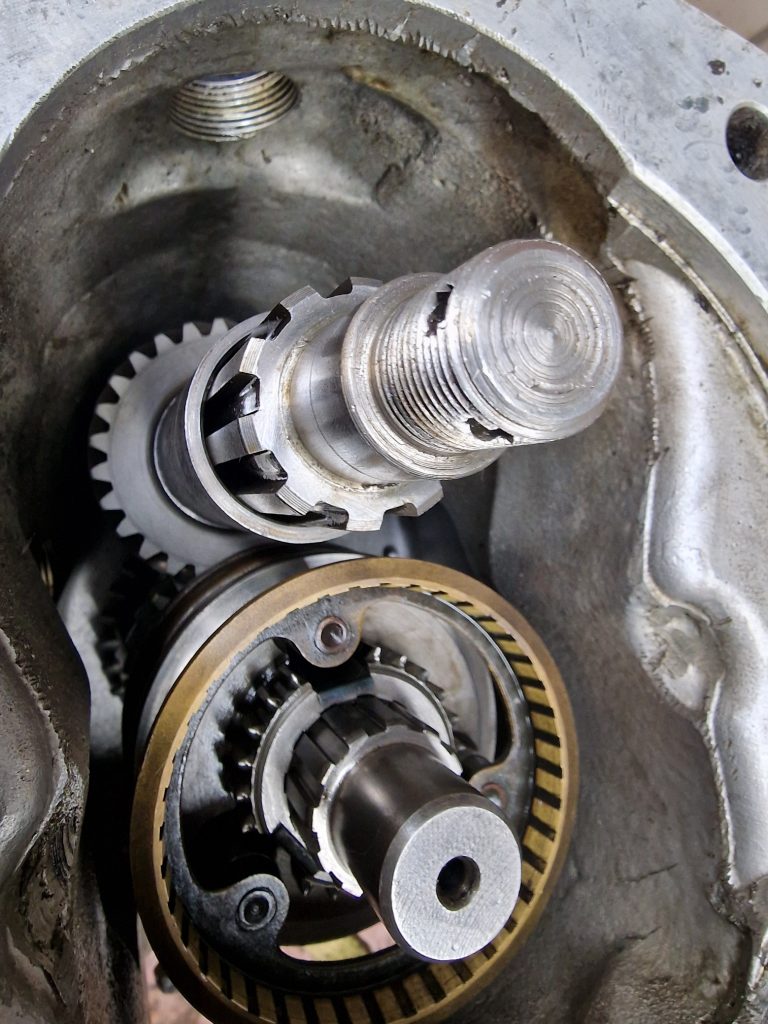
Next up is to position the 3 shafts into the output housing, being careful to ensure that the coupling is positioned correctly. Also remembering to put the 4wd locking dog in.
This is the coupling and shafts.
Once they are in, its simply a case of offering the whole thing upto the transfer case, and bolting it all up. Well, easier said than done. Firstly, there is a big spring in there keeping the two parts apart, secondly we need to put the Front Output shaft in, and locate it into the 4WD locking dog, as well as putting a gasket between the two cases and not breaking it and finally locating the selector shaft through the selector.
Did a dry run first, before adding the gasket, also to make sure that it all seemed to work before committing.
Once it was all in, bolted it up and tested the selector shafts again. I’m pretty sure they are all working as they should, selecting low/high range and the 4WD selector kicking in when it should.
Fitted the rear output flange, and handbrake back plate, and finished off the front with the forward flange, the 4WD selector lever and the dust cover for the shafts. Also put the Low/High lever in position and tried on the new 4WD lever.
Put the bottom cover plate back on the transfer case, just to keep it safe and all together as this will need to come off later, and the intermediate gear out again when its attached to the main gearbox.
Everything tested ok, I guess I will only know if its completely right when it is put into use for the first time. The only thing I might change is to get a new 4WD pin, the old one is a little cruddy, and a little tight in the hole, no big deal, easy enough to change later, and not expensive.
So thats the Front output housing and transfer box pretty much sorted. What I should have mentioned was that I changed all the seals, just in case. Next job, onto the main gearbox.