May 2026 – Various Bits of Stuff
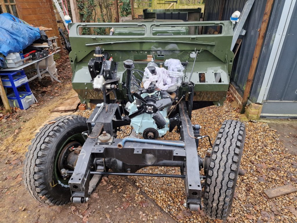
This one is going to go all over the place, I finished up the electrics in the last one to keep that separate. Will try to keep is short and sweet, but no promises. Ultimately however with all the stuff in this one, and previous articles about electrics, when I do finally start, or attempt to start the engine, if it does run nicely, I would potentially be able to drive Isobel round the garden, albeit with no brakes.
So hear goes.
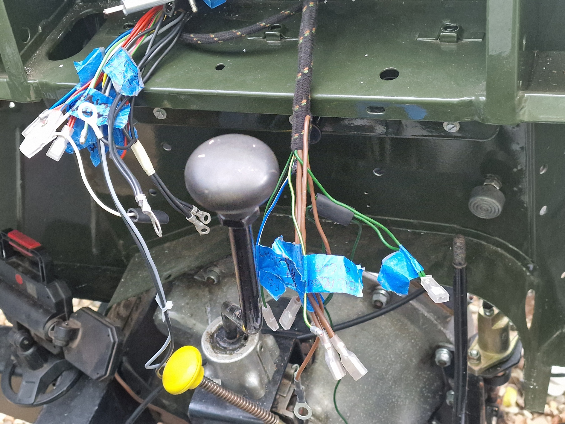
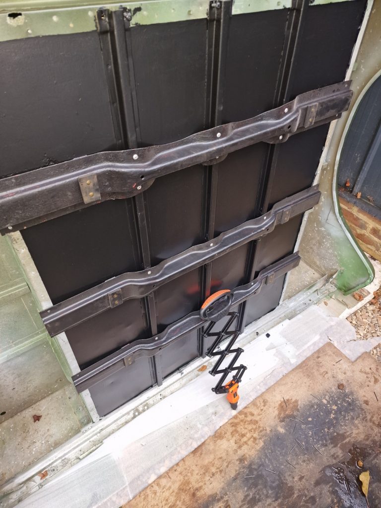
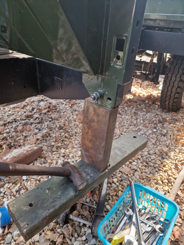
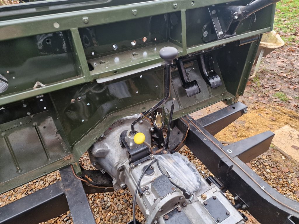
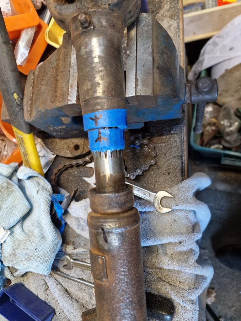
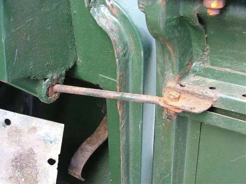
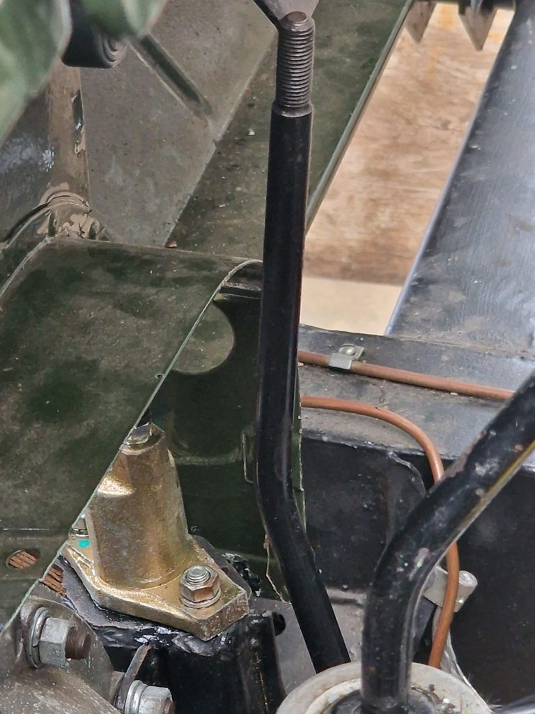
First up, and in no particular order is the Low/High gear stick. I cant remember if I mentioned it before, but with the gearbox in the car and the bulkhead in-place, pushing the gear lever forward to select High Range, it fowls against the bulkhead, ad only just engages. I did post a question on the series 2 club forum, and the answers, one in particular was surprising. While I asked something slightly tongue in cheek, got a surprising answer. What I asked was, were the different profiles of HL gear sticks, and guess what, yes there are about 6 different profiles, all slightly different and some bent other not, longer and shorter brackets on the bottom, all sorts.
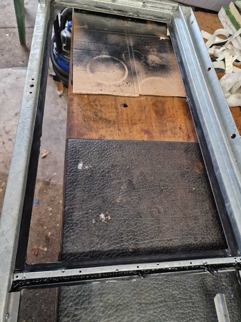
Anyway, what to do, well I decided to bend mine…
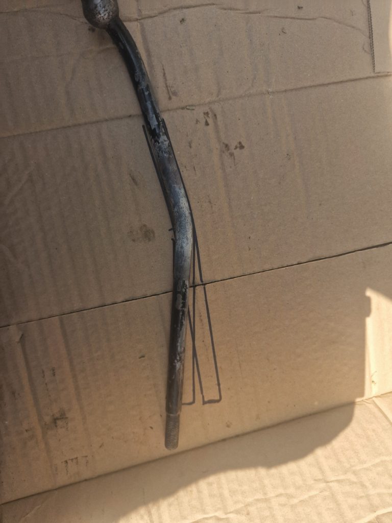
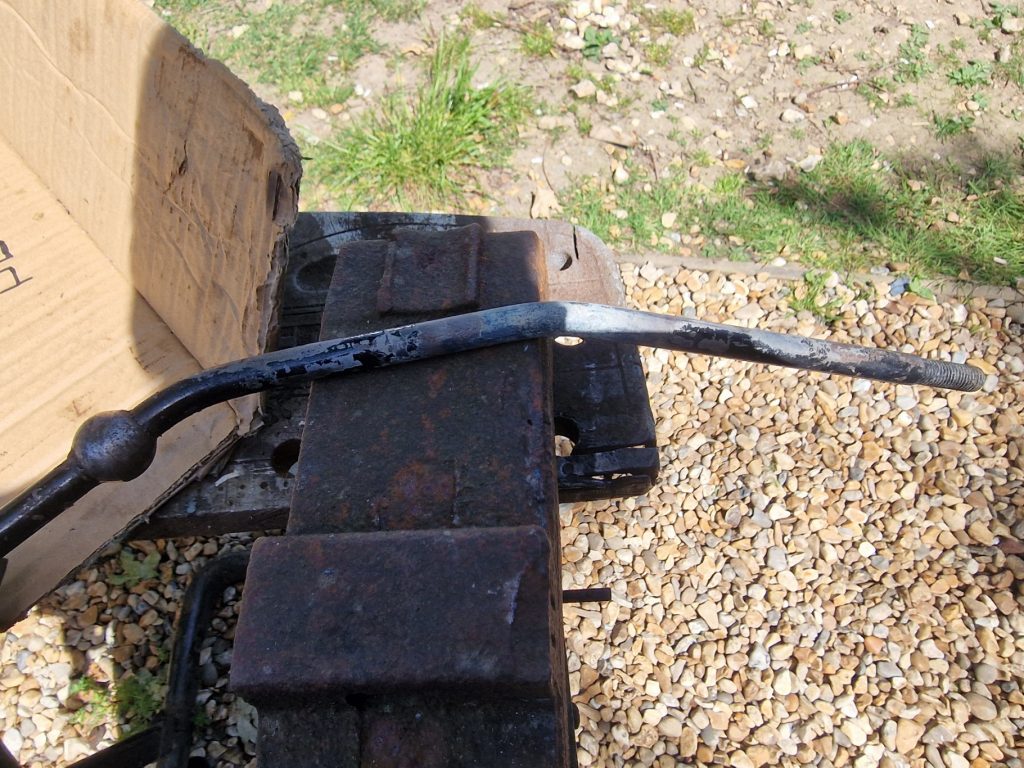
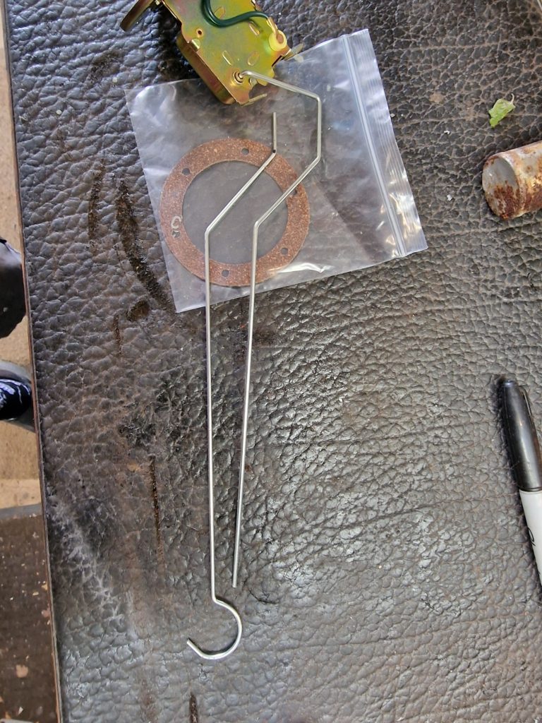
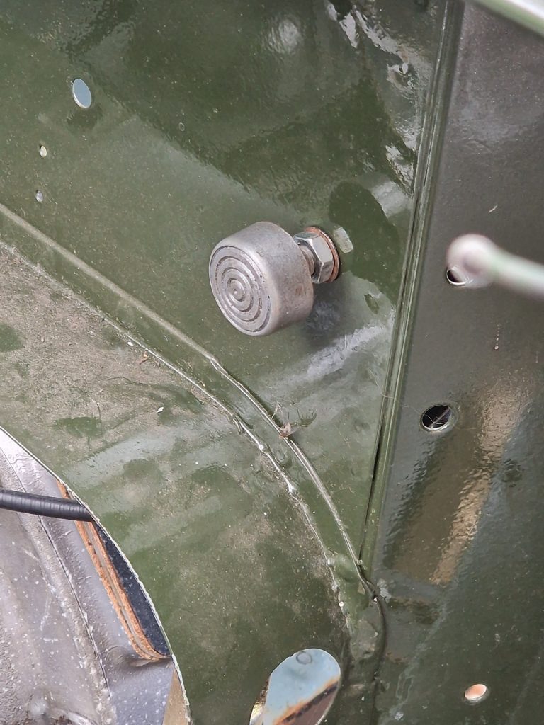
You can see by the image on the left, how much I bet it, took two attempts to get it to a profile that didn’t fowl the bulkhead. Here it is back in-place, fully forward engaging high ratio.
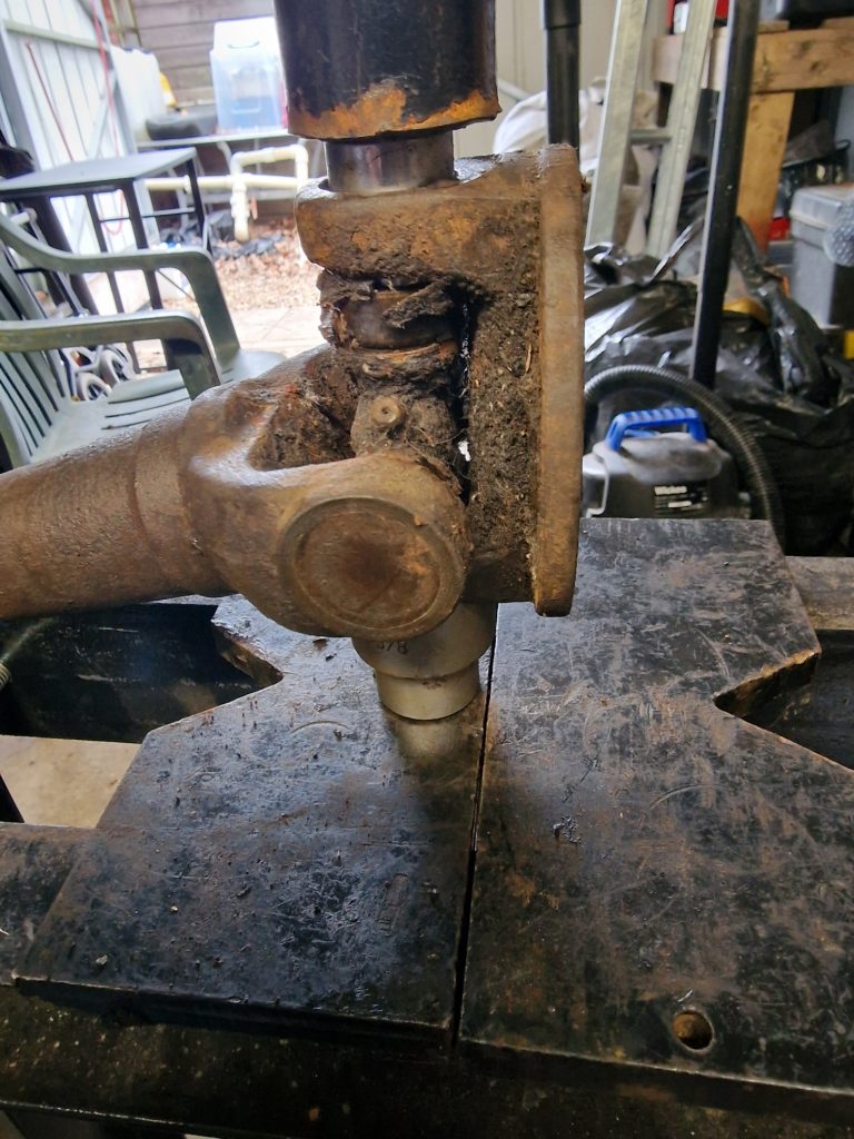
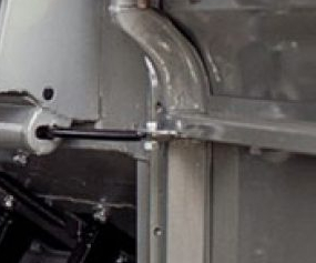
Clutch
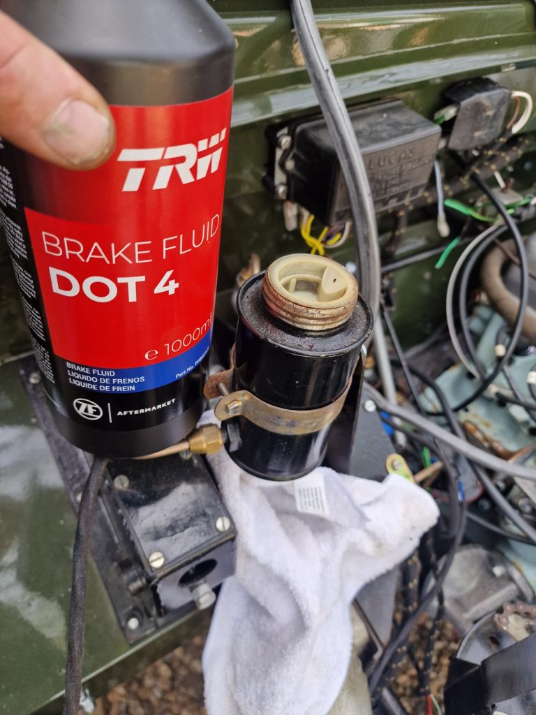
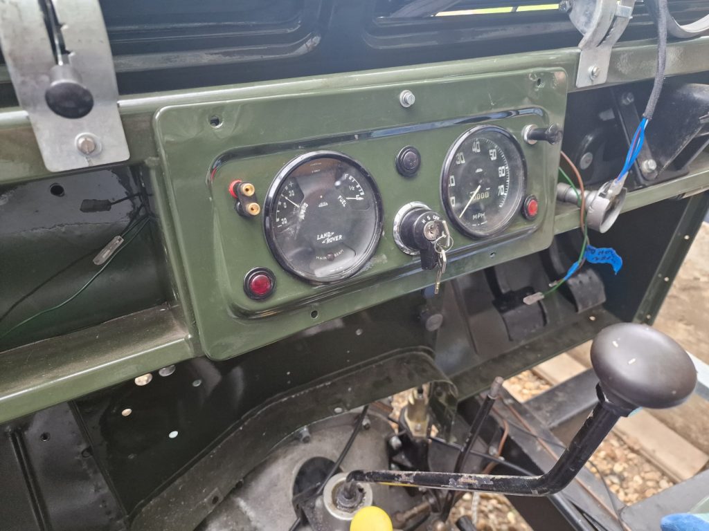
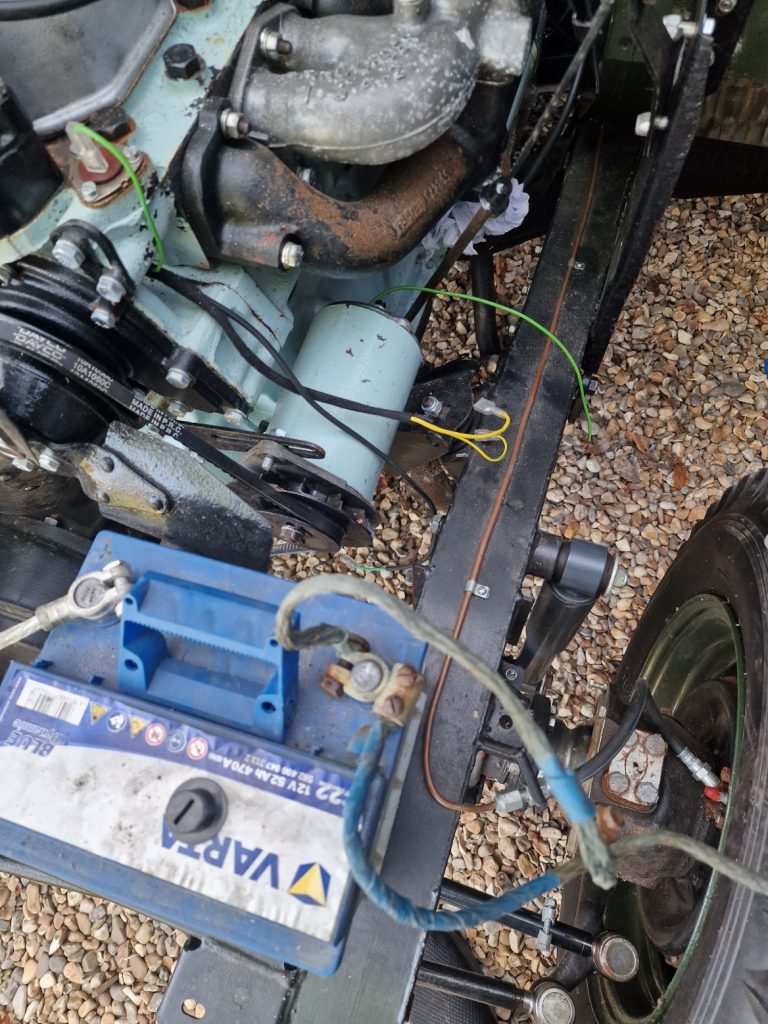
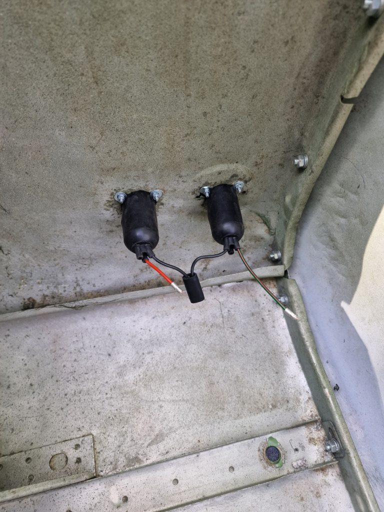
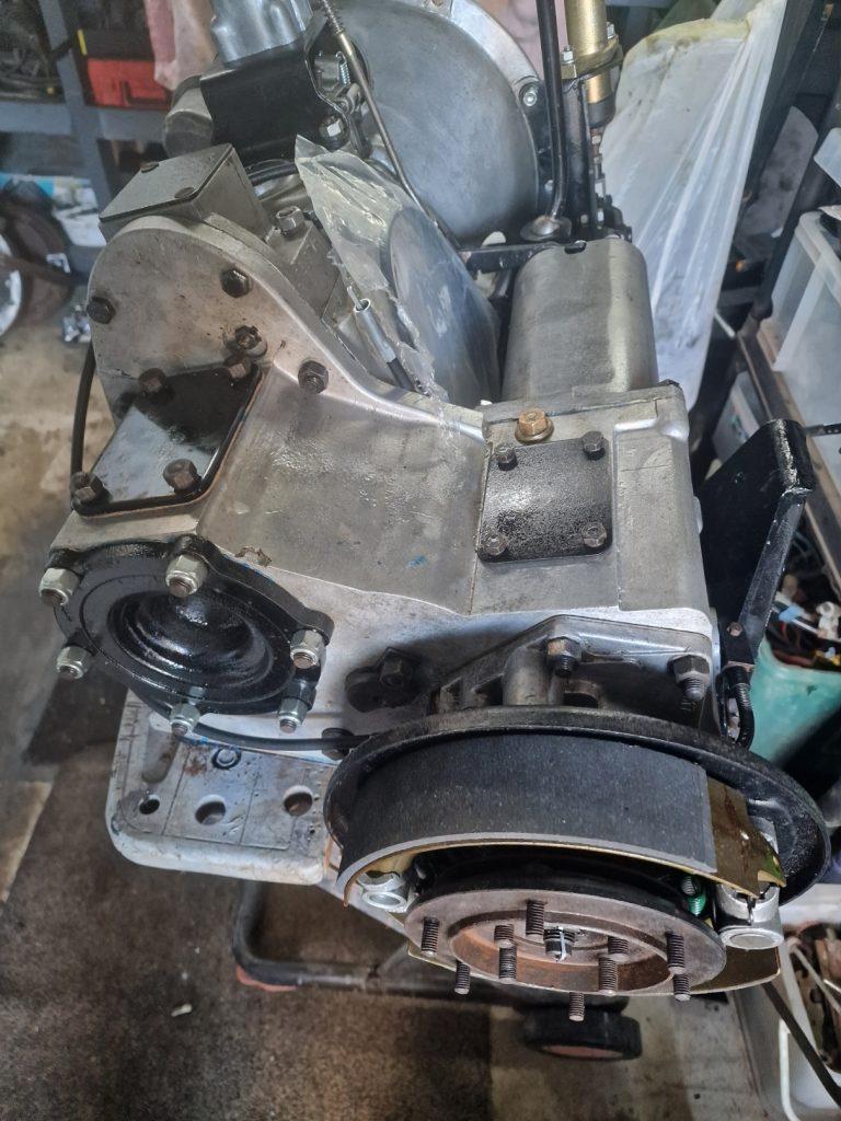
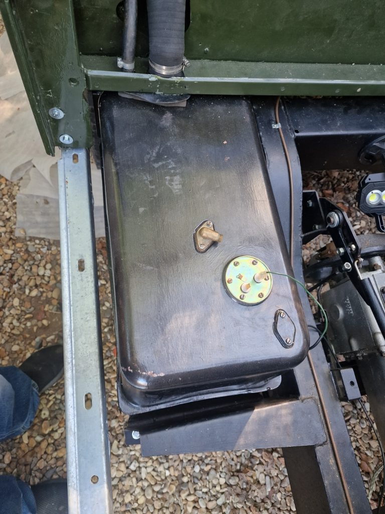
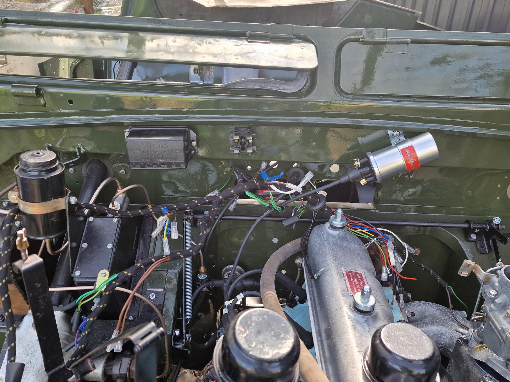
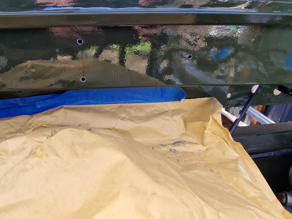
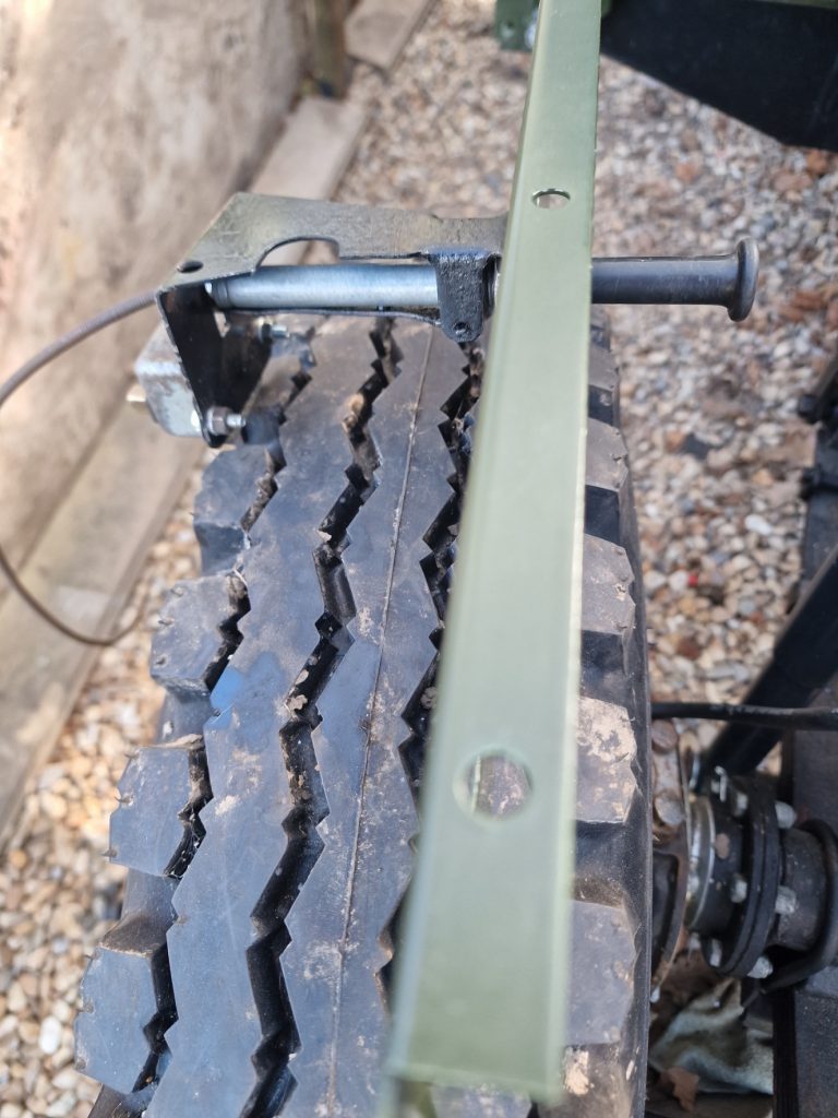
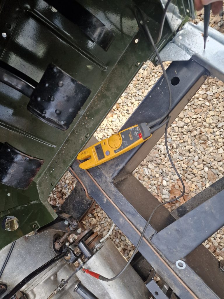
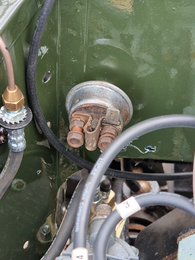
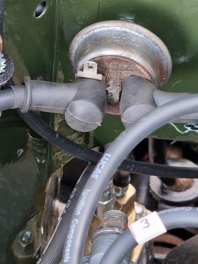
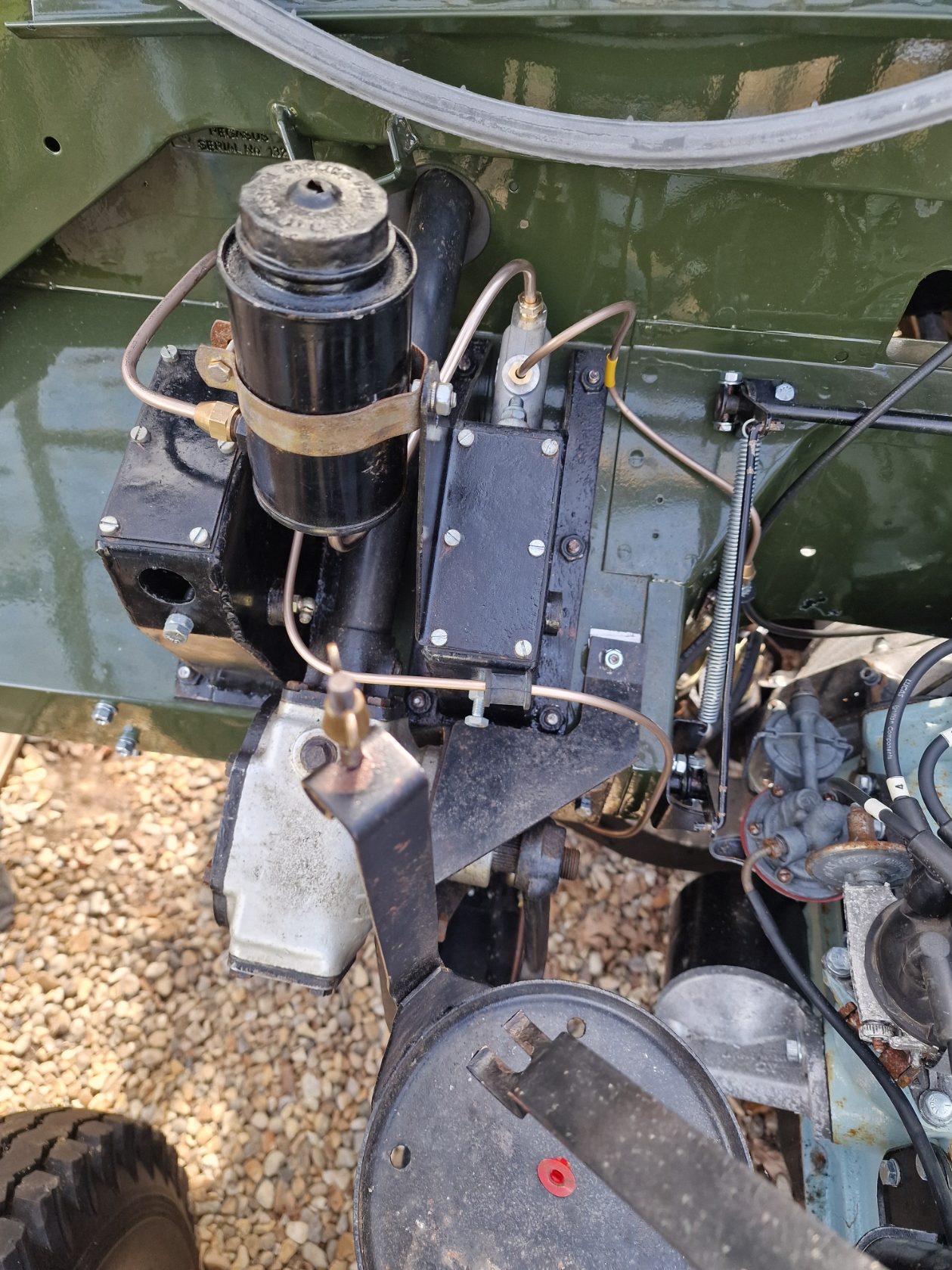
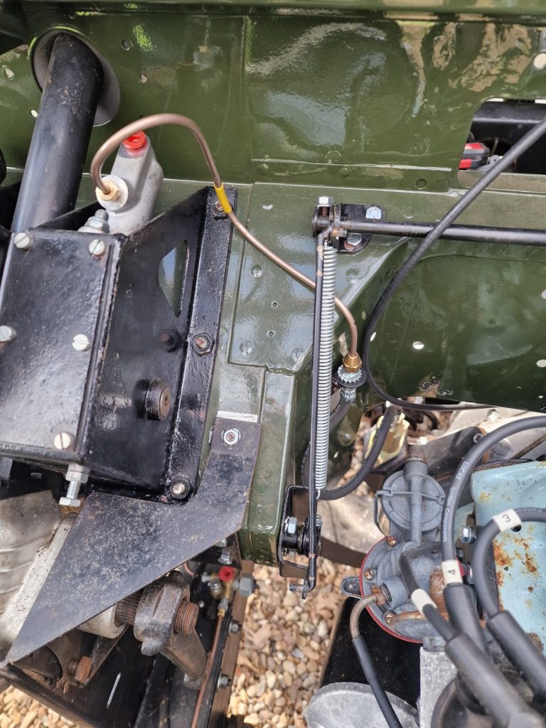
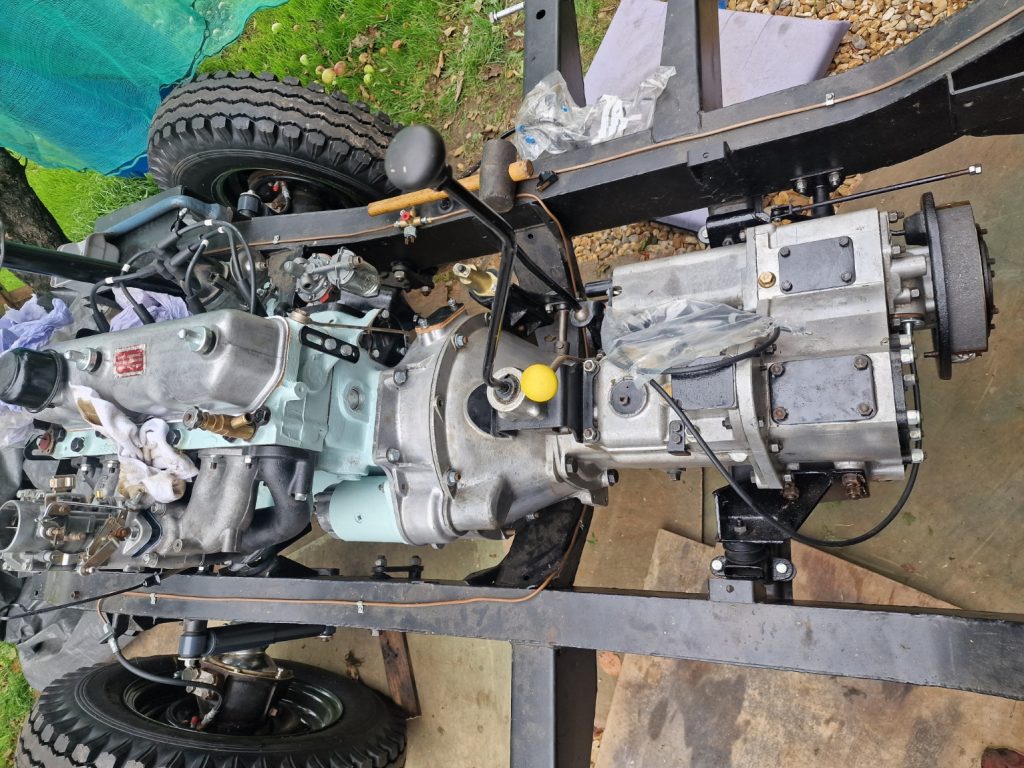
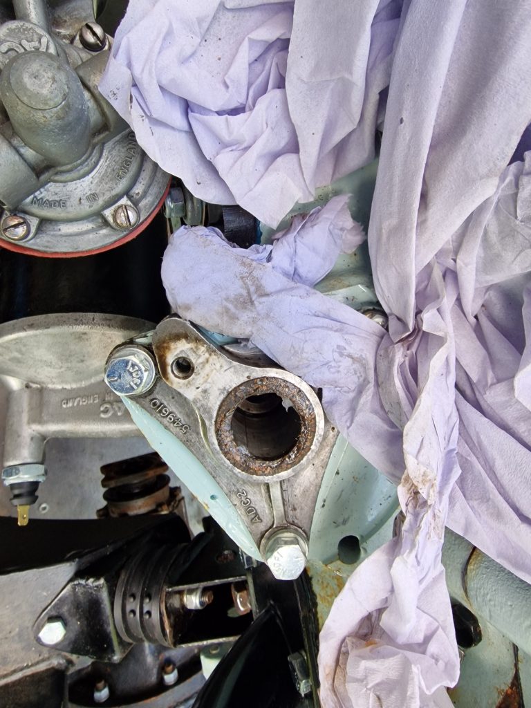
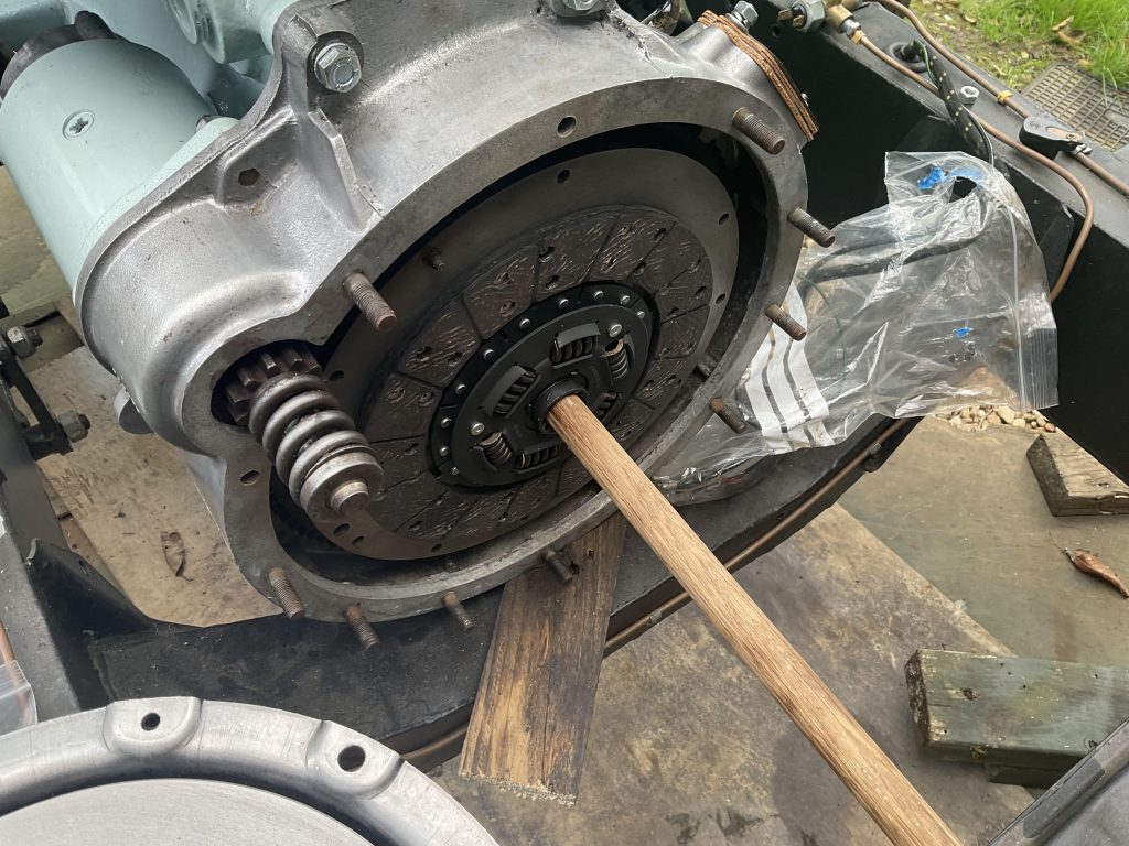
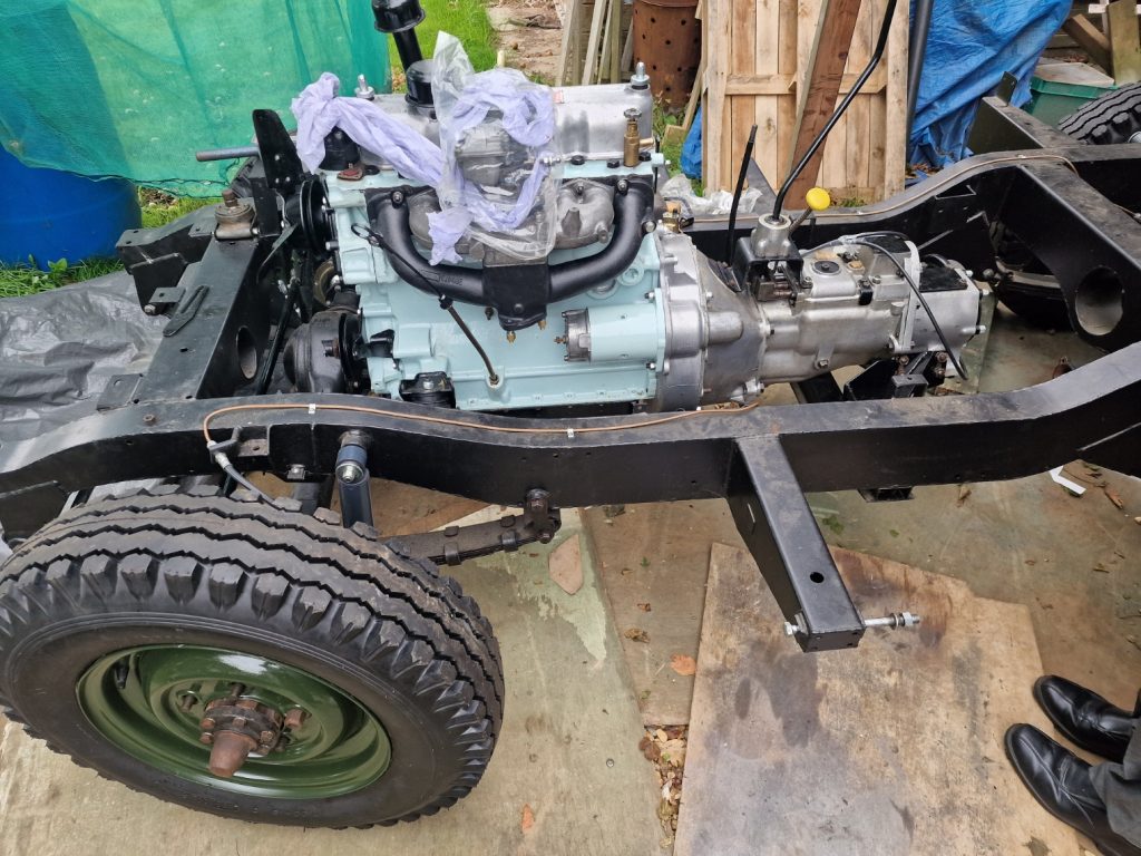
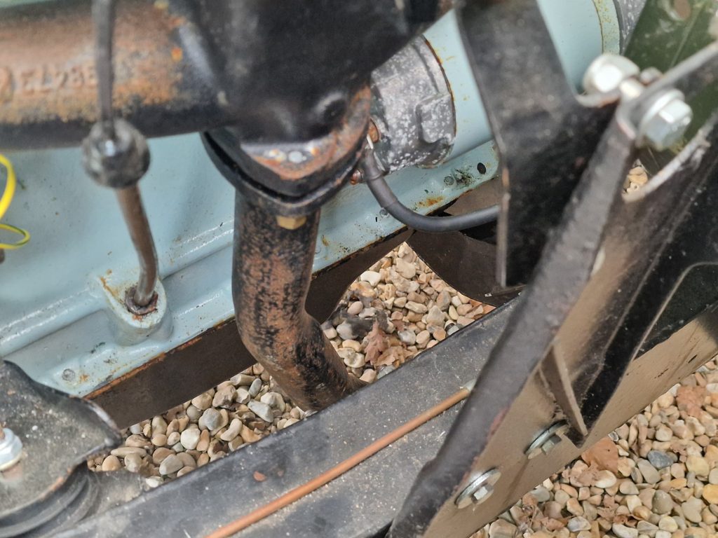
Next up, simple one. All I needed to do was to poor in some brake & clutch fluid, bleed the the system at the clutch slave cylinder (You can see that in the picture above just about, with the bleed nipple just about in shot).
I bought a very simple bit of kit, a plastic pipe, with a none return valve inline.
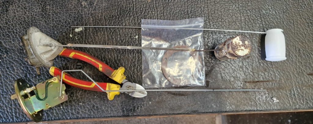
All I did was attach the bleed pipe to the bleed nipple, put the other end into a glass jar (which eventually had a little bit of fluid in), topped up the brake ad clutch reservoir (pictured) and kept it topped up thoruhg the process.
With the nipple open, pumped the clutch peddle a few times until no more air was coming out and then tightened up the nipple.
Thats it. Tested it by putting it into gear, and manually tried to rotate the gearbox output shaft. Of course, when the clutch was not pressed, it would not move, but press the clutch peddle in, it does. Now it will need a little more setup, but fundamentally it works.
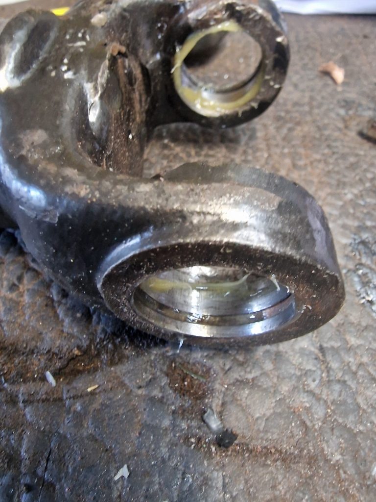
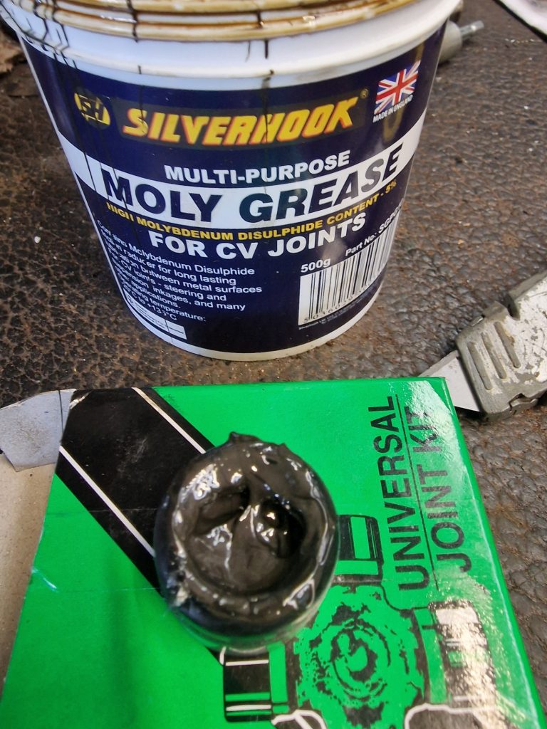
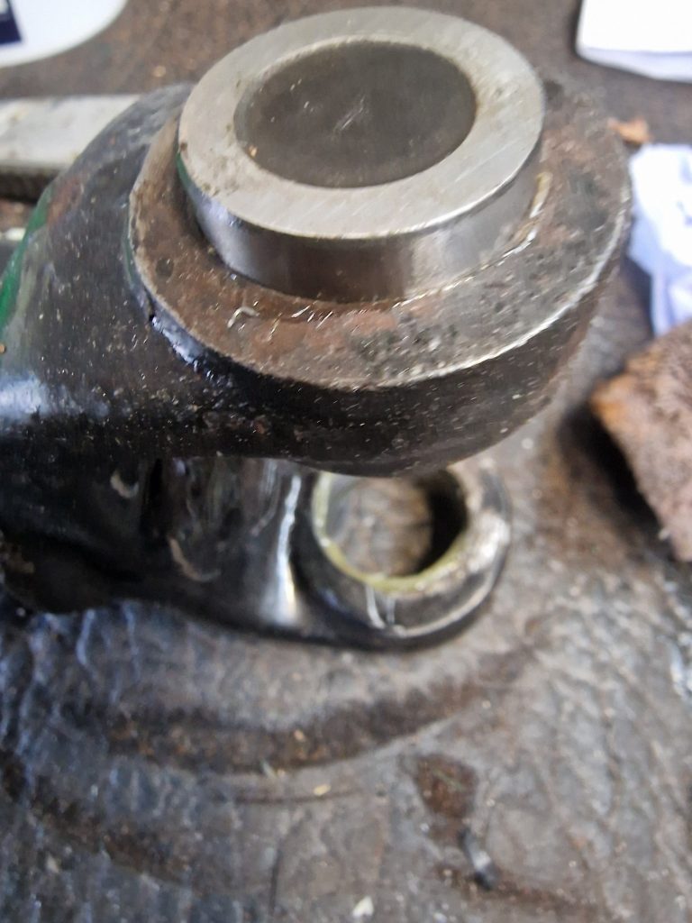
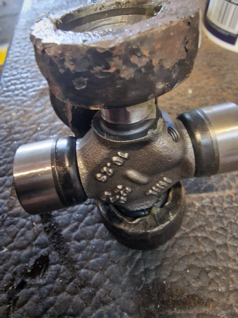
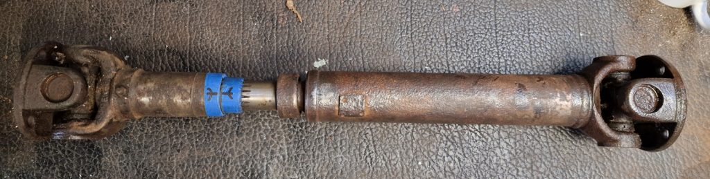
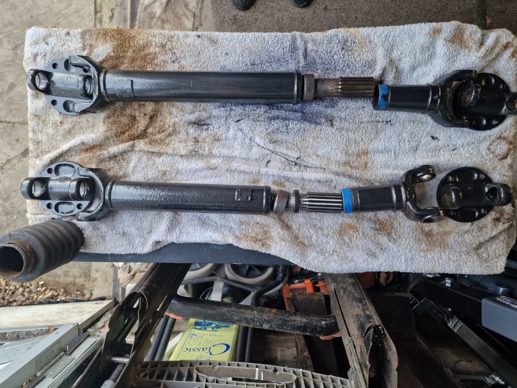
Propshafts
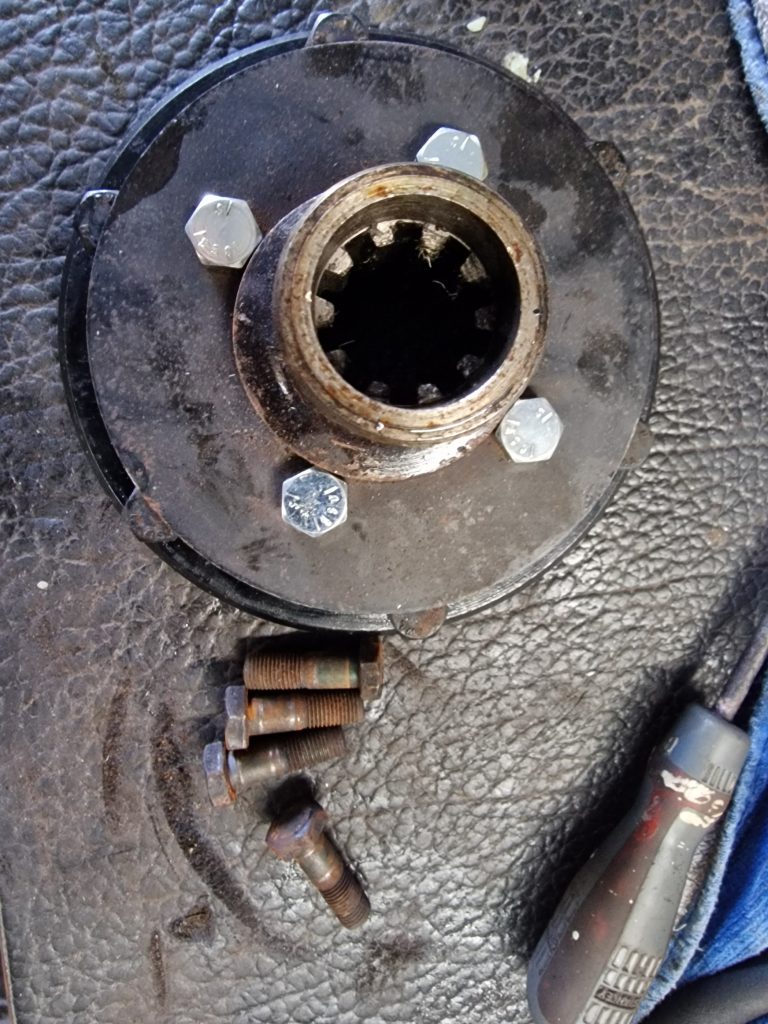
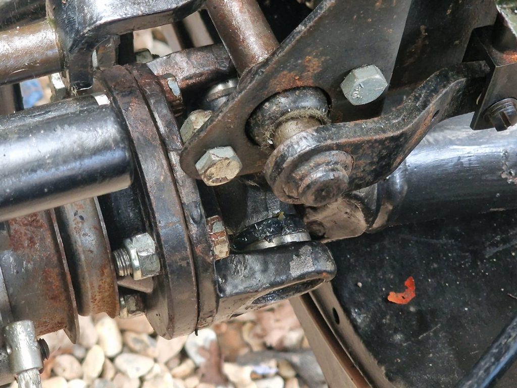
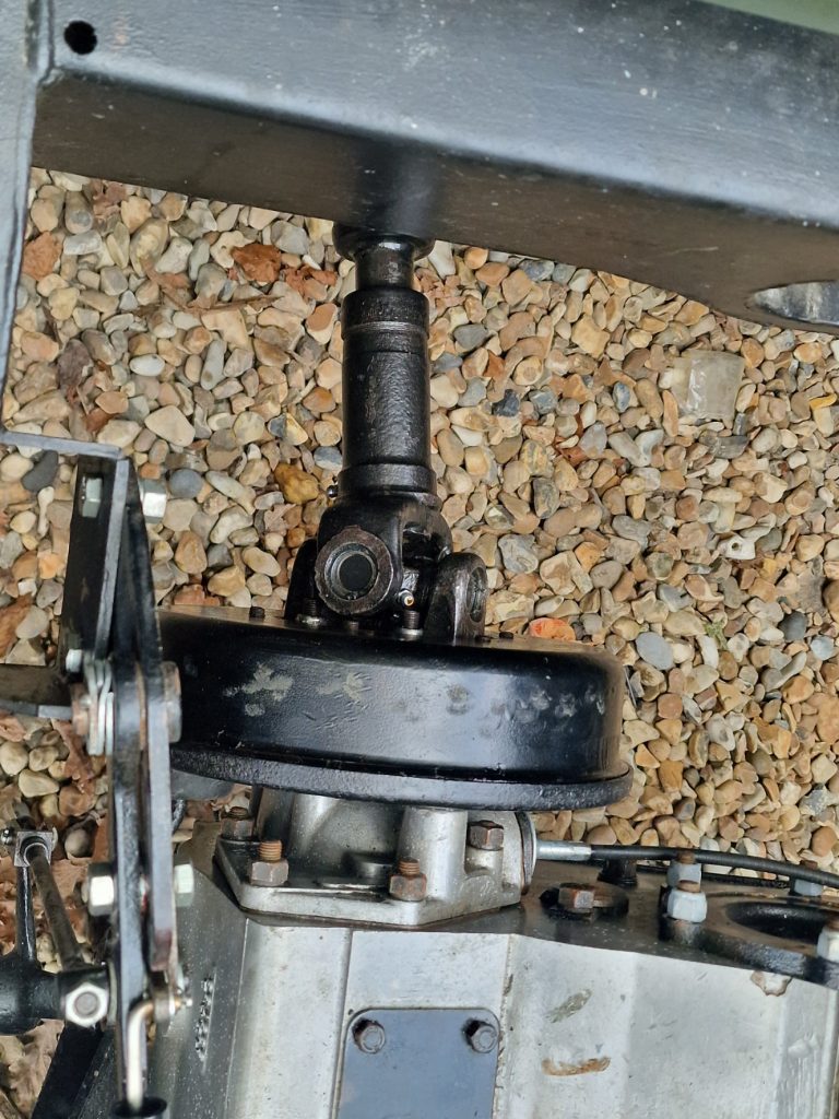
Bit longer this one. I replaced the UJ’s on both Propshafts (twice) sometime ago, I also purchased two sets of Propshaft bolt sets, one for the front prop, one for the rear.
So I set about putting the rear prop shaft on. Ok, so heres a catalogue of errors.
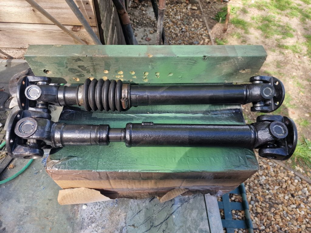
- I bolted the rear pro to the gearbox, I did think these bolts are a little short, ok, must be ok. Then went to bolt it to the rear axle. 1st school boy error, wrong propshaft, the front and back are different lengths, I was trying to put the front prop onto the rear.
- Took it off and re-bolted the correct prop to the gearbox. Bolts still seemed a little short. Went to bolt it to the rear axle, and realised the bolts left in the pack for the rear prop are too long.
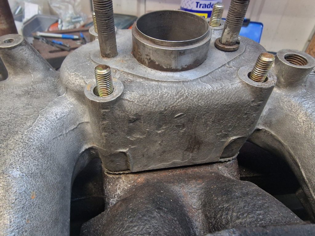
- Had to remove the prop, remove the back of the gear box and replace the bolts, as they are fixed into the dear drive shaft.
- Finally, started to make some progress
- Last lesson, I should have bought a special socket that allows it to get past the UJ’s, so had to resort to spanners, which took an absolute age.
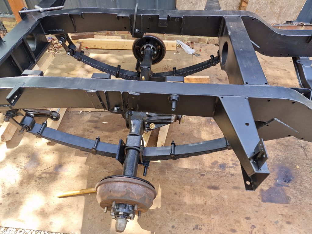
Anyway, finally got the rear and front prop’s on. I did need to jack up the front and back wheels on one side so I could rotate the gearbox to align the front prop’s bolt holes.
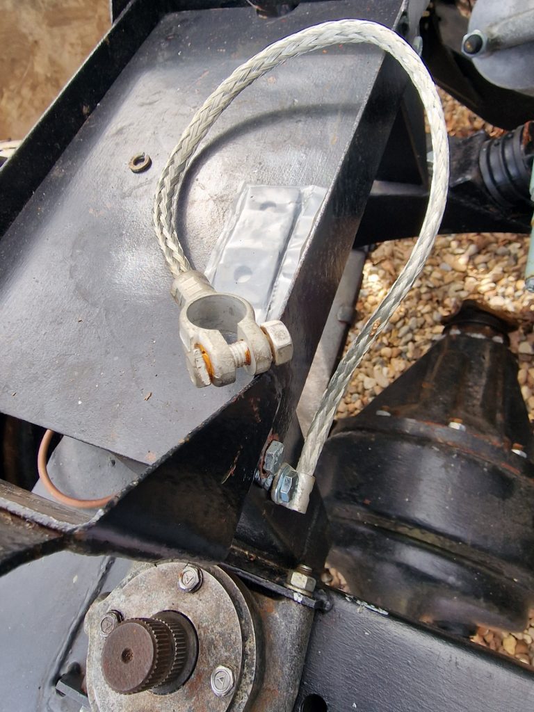
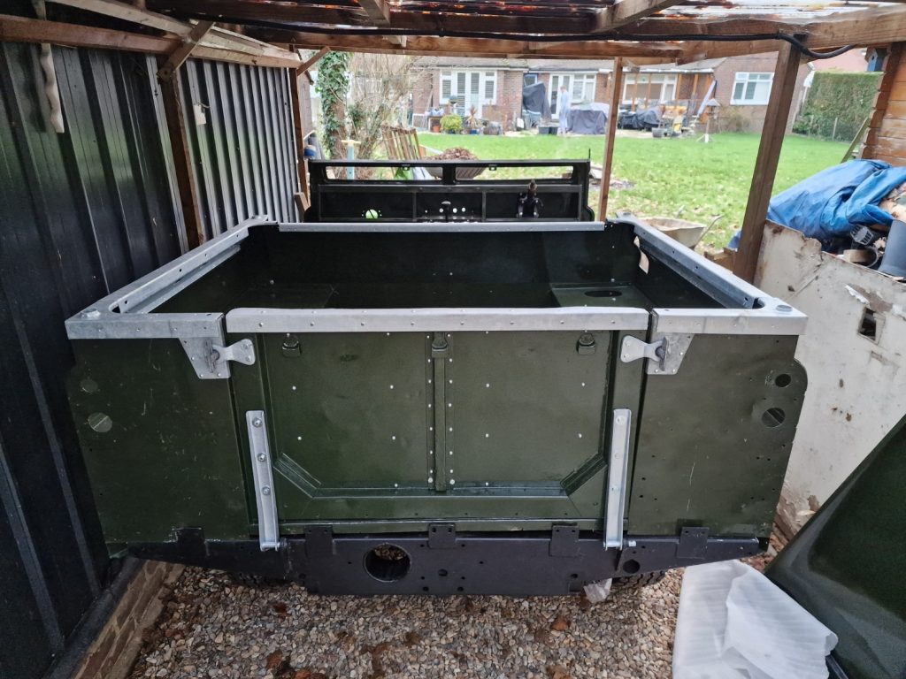
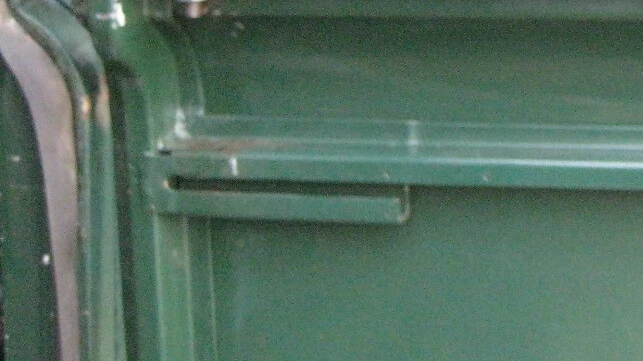
Towbar
Nothing is easy putting this ting back together.
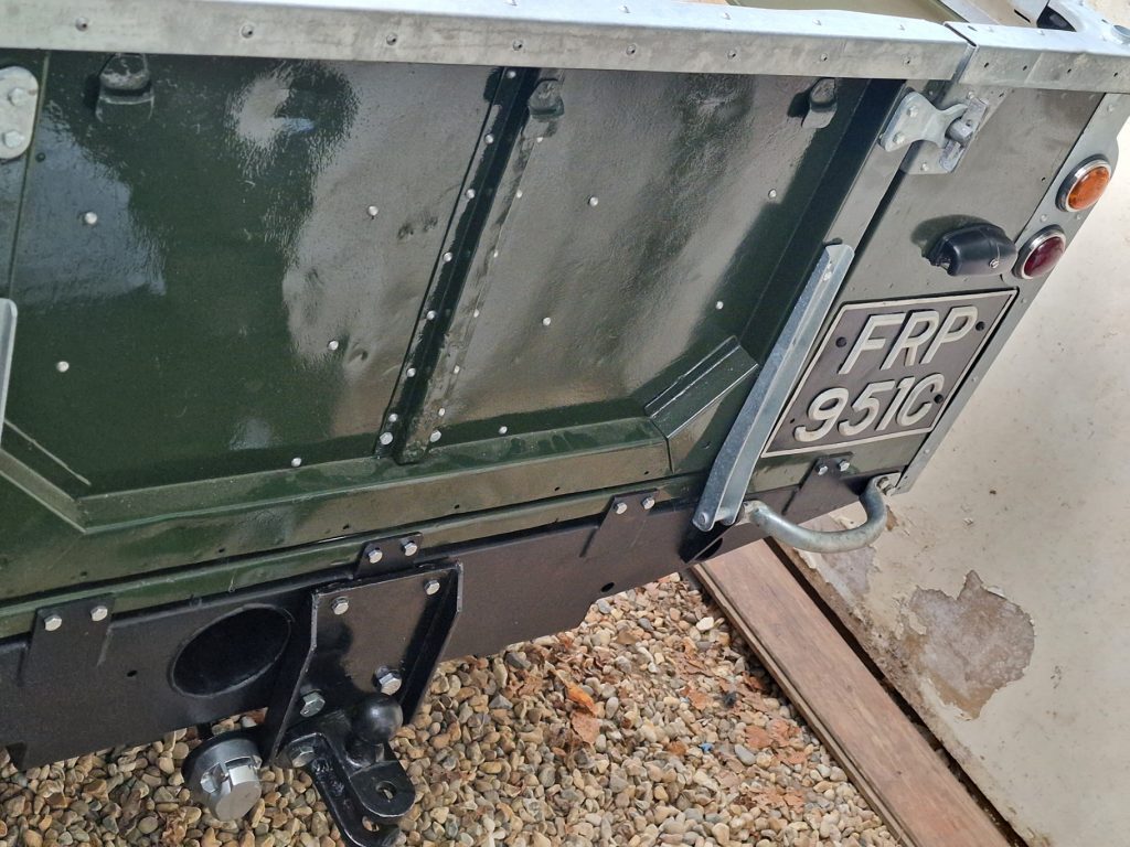
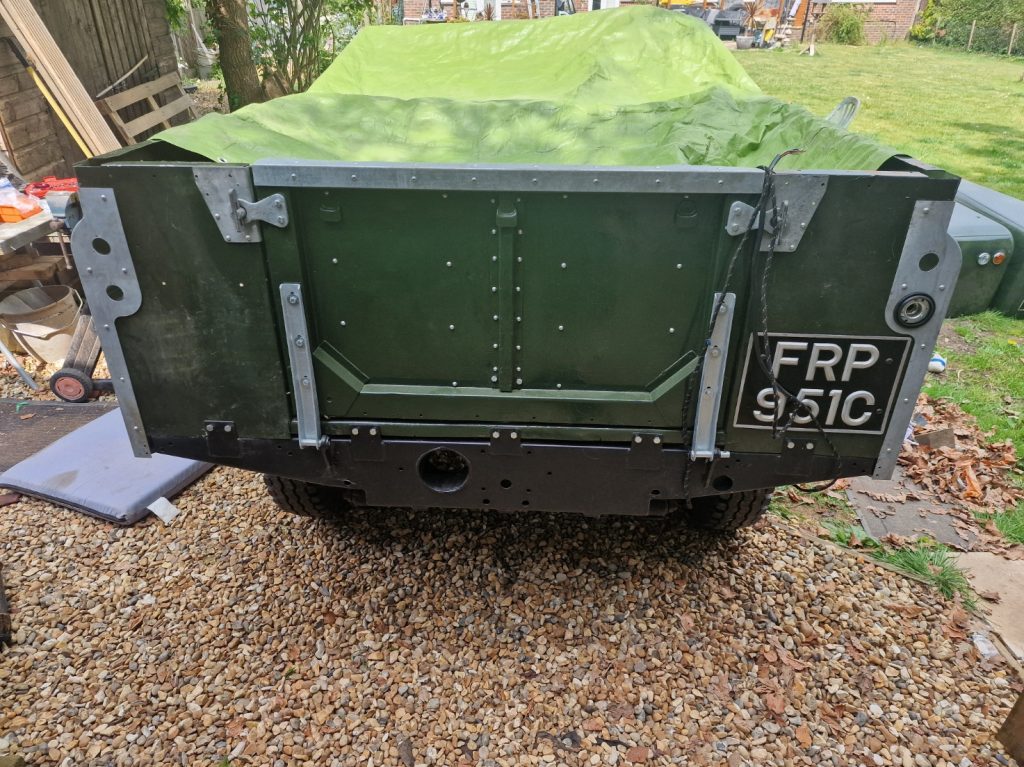
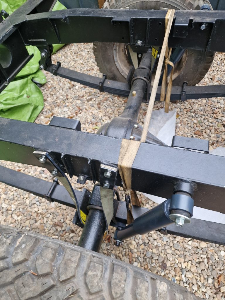
Here’s the final thing.
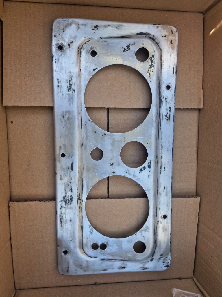
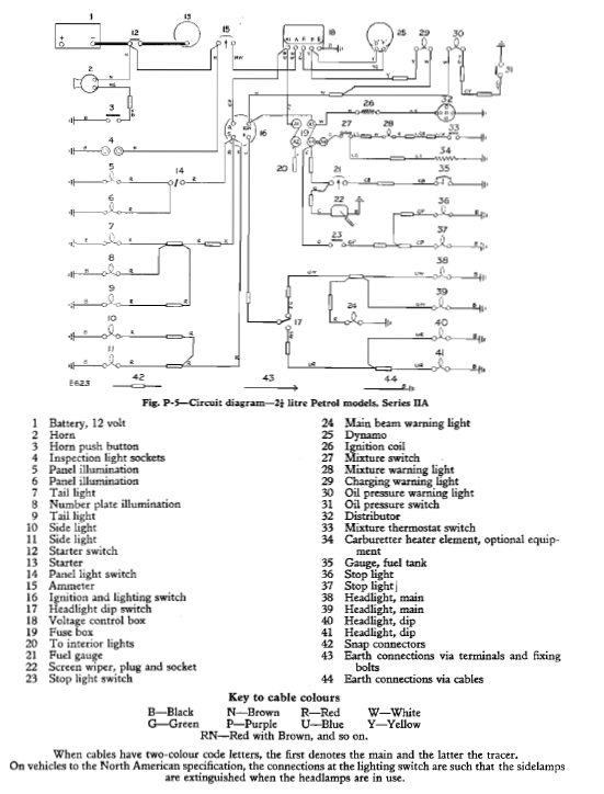
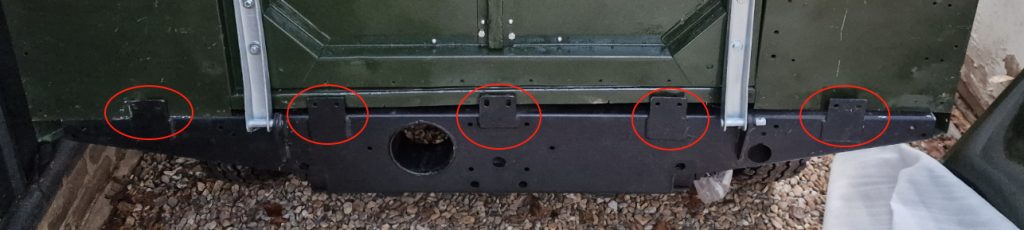
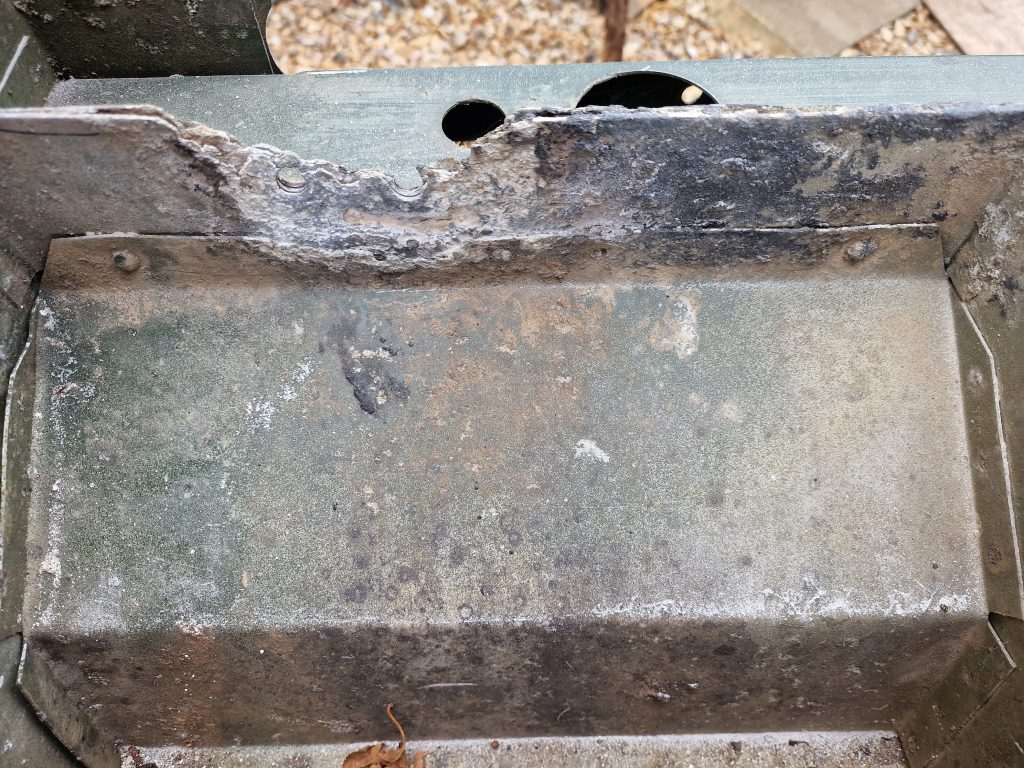
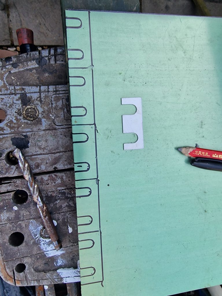
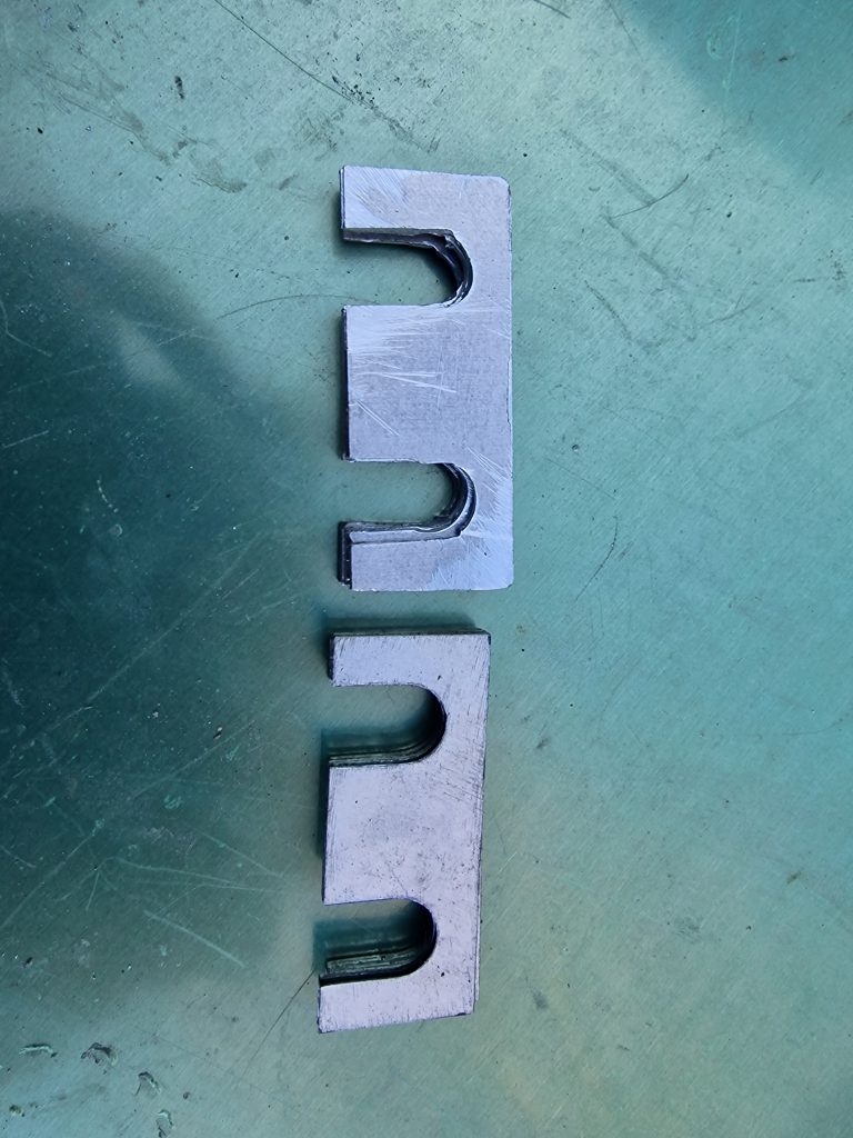
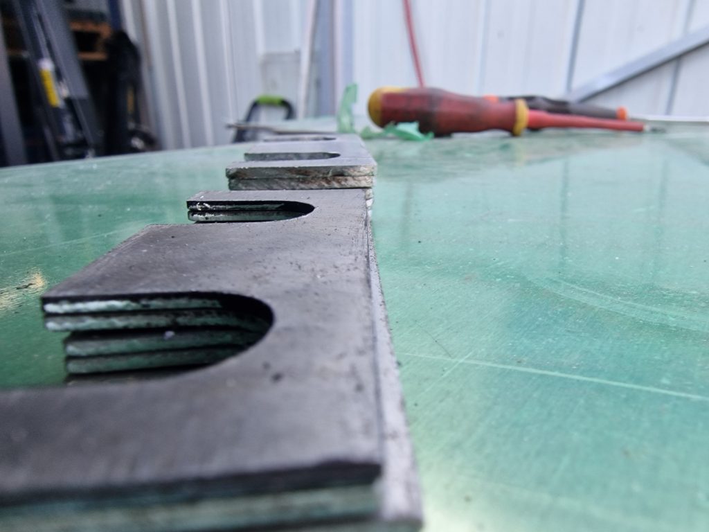
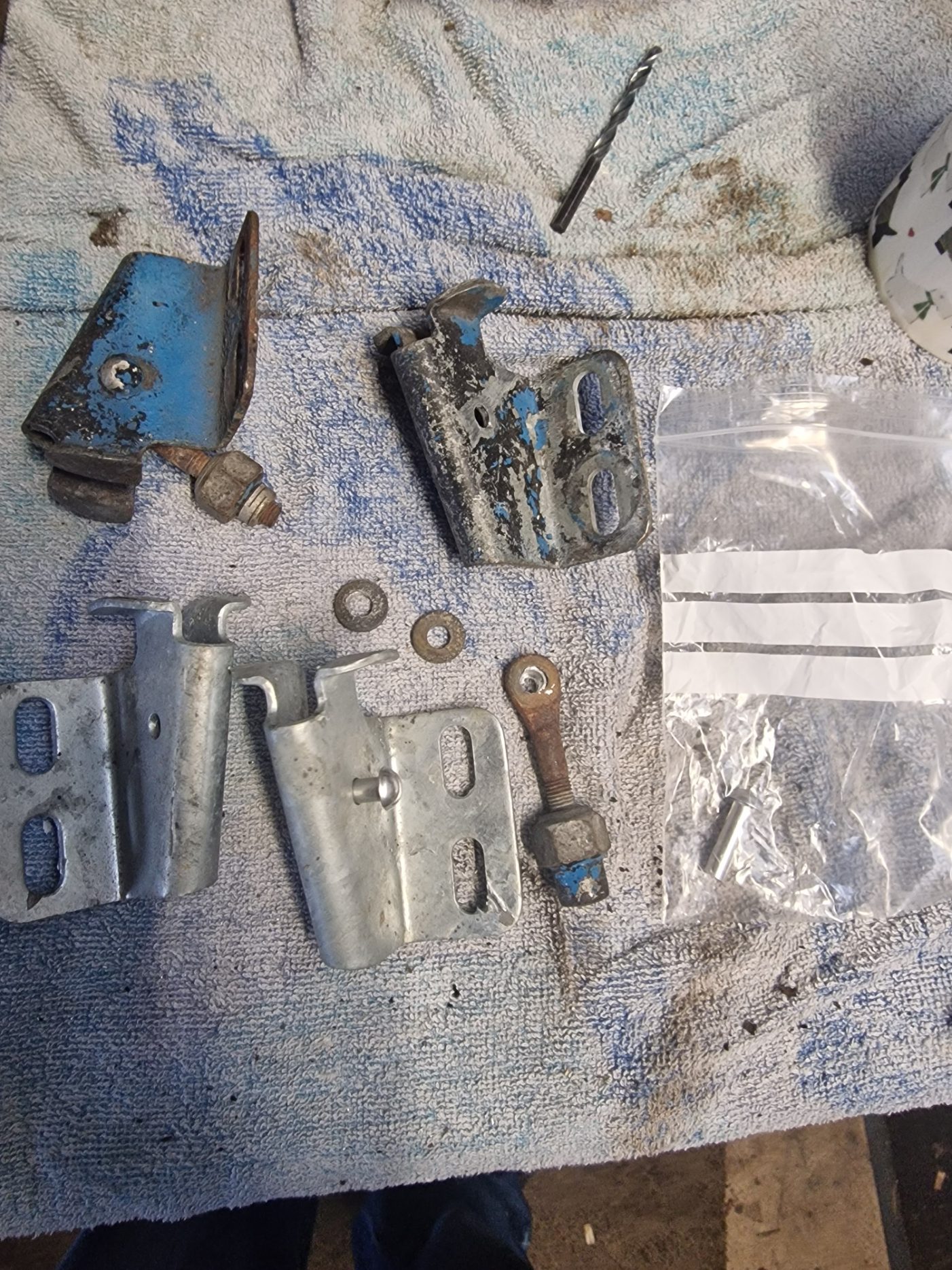
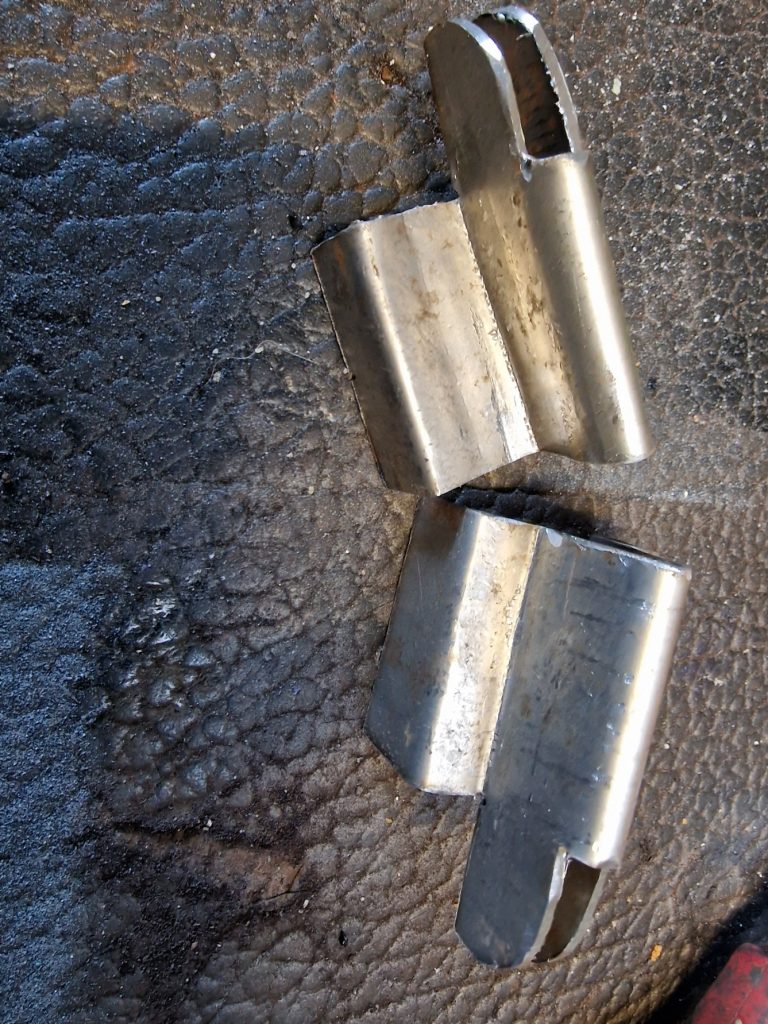
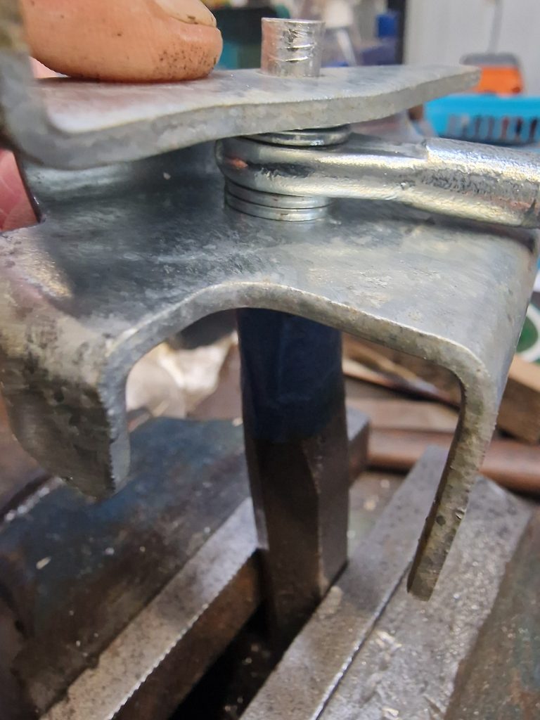
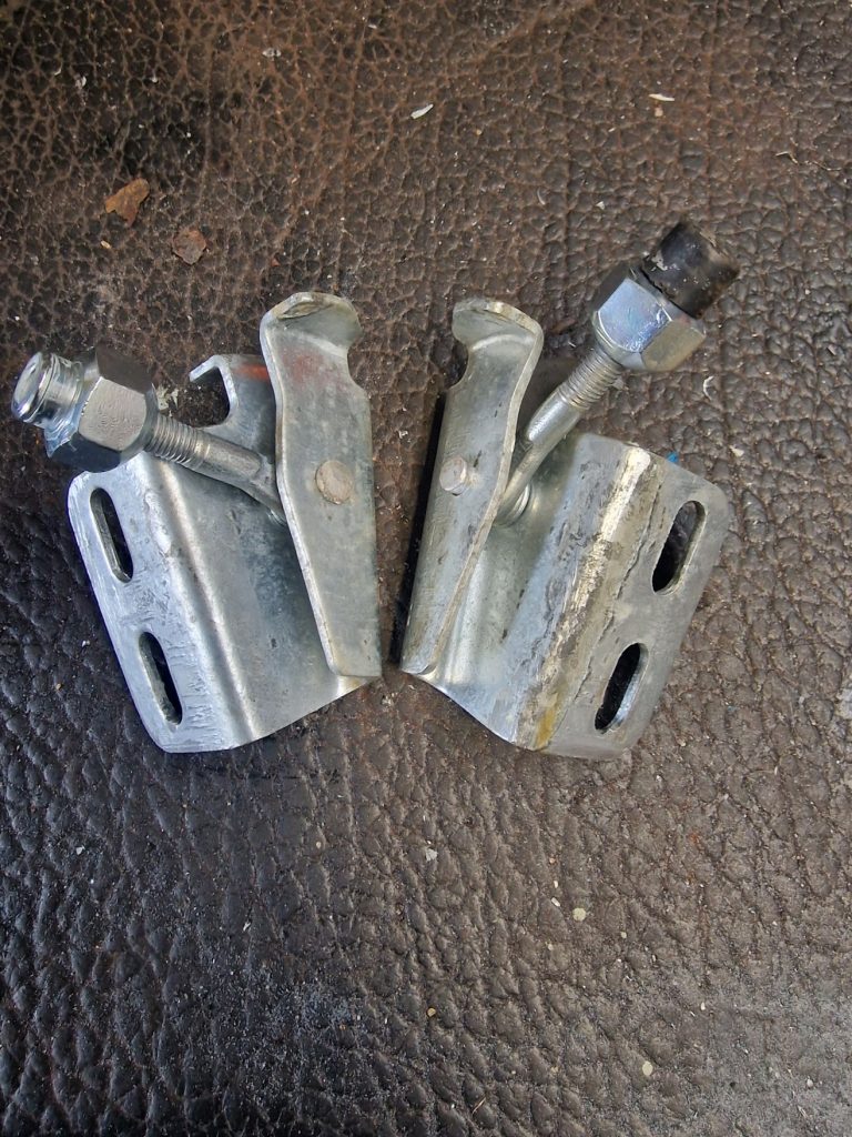
The issue with this is that of course it needs to be bolted on very securely. When I read about this, people suggested that there needs to be spreader plates on the back of the crossmember, so I had to hunt through all my saved junk (I haven’t thrown anything away yet) to find them. I knew I had them as I took a picture of the towbar when I took it off.
Found them, cleaned them up, painted them.
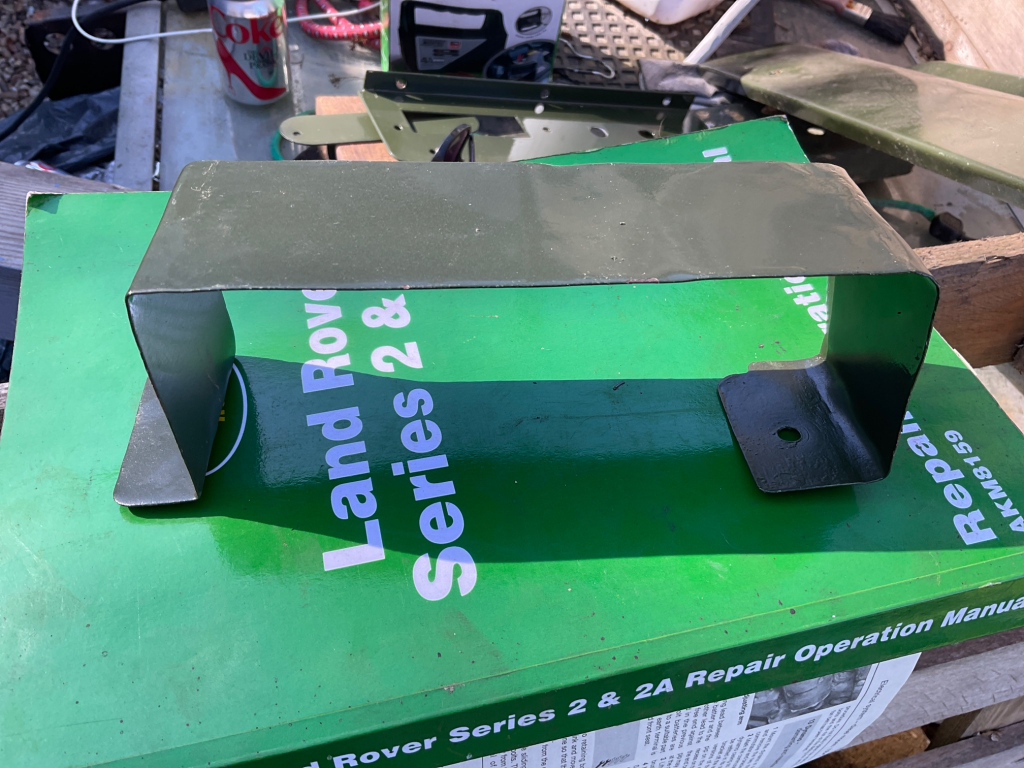
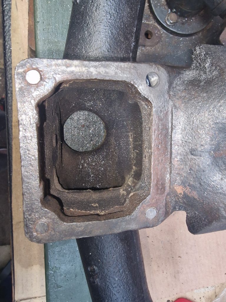
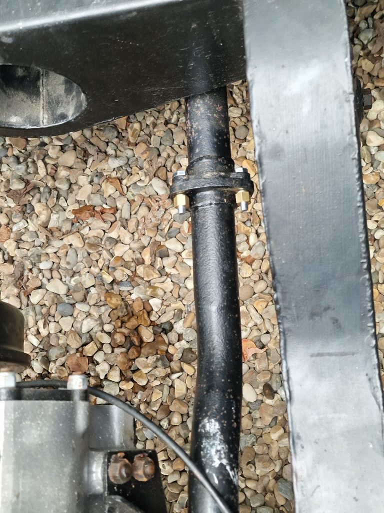
The other issue, is that at the back of the cross member there is a channel, with a small v cut out to allow the bolt to go all the way though.
The challenge here is that the bolts need two nuts on, but two nuts wont fit in the channel, as well as the spreader plate. So decided to buy some heavy, high tensile lock nuts. Amazingly, with the Spreader, a washer and the lock nuts they just about fit into the channel, so finally manage to get it bolted on.
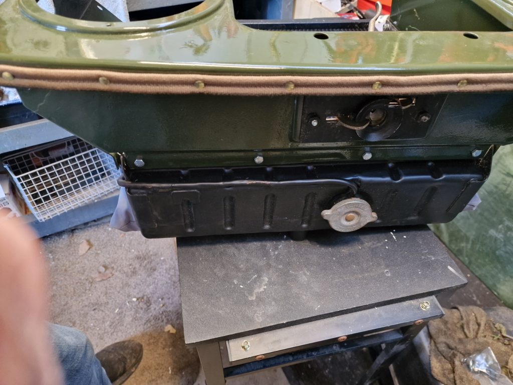
Exhaust
Nearly last for this one. Finished putting in the last part of the exhaust system.
I didn’t add any sealer on the exhaust joints for now, will come back to that later along with many other things, but my focus for now is to get it pretty much all together.
So now, if the engine does happen to start, technically I could drive it.
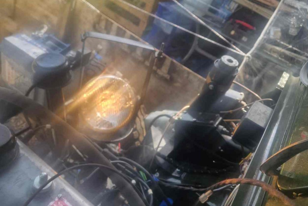
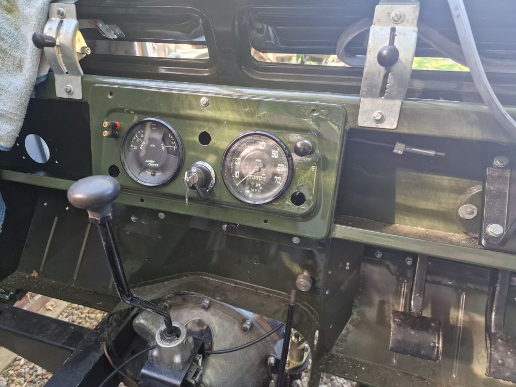
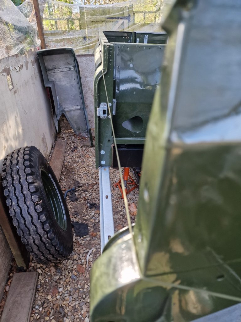
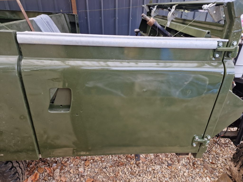
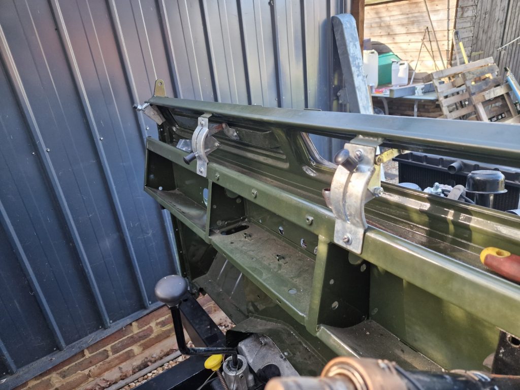
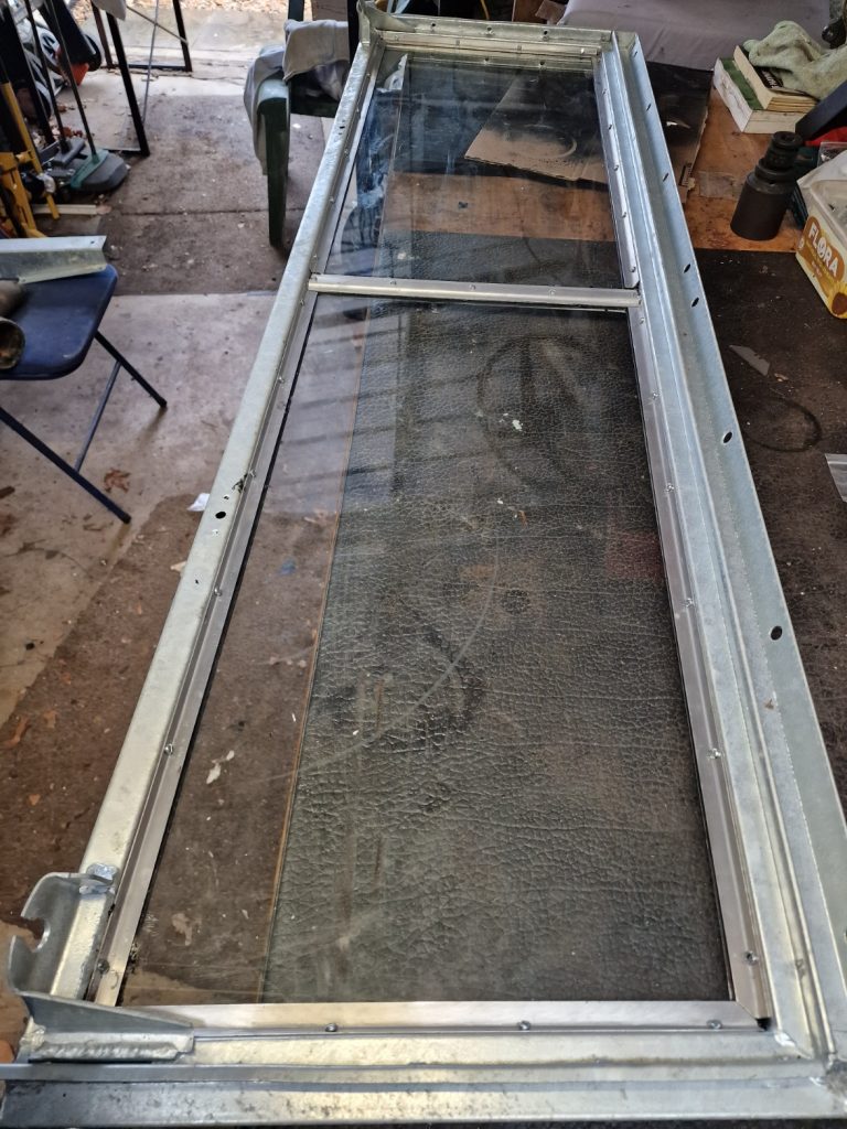
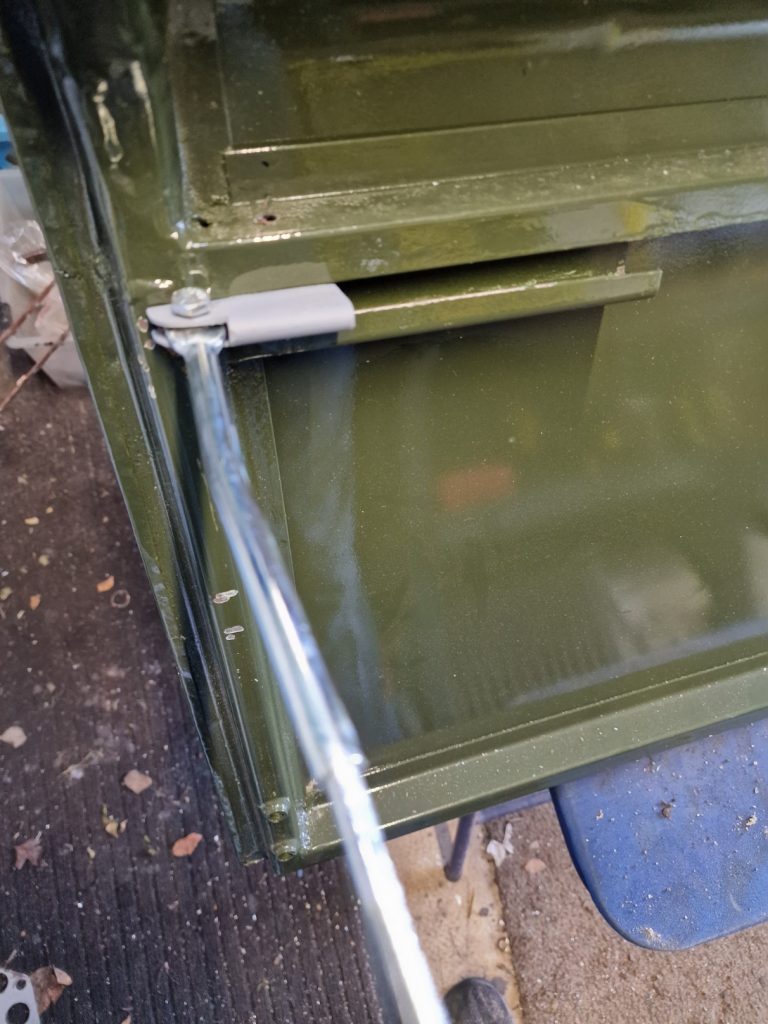
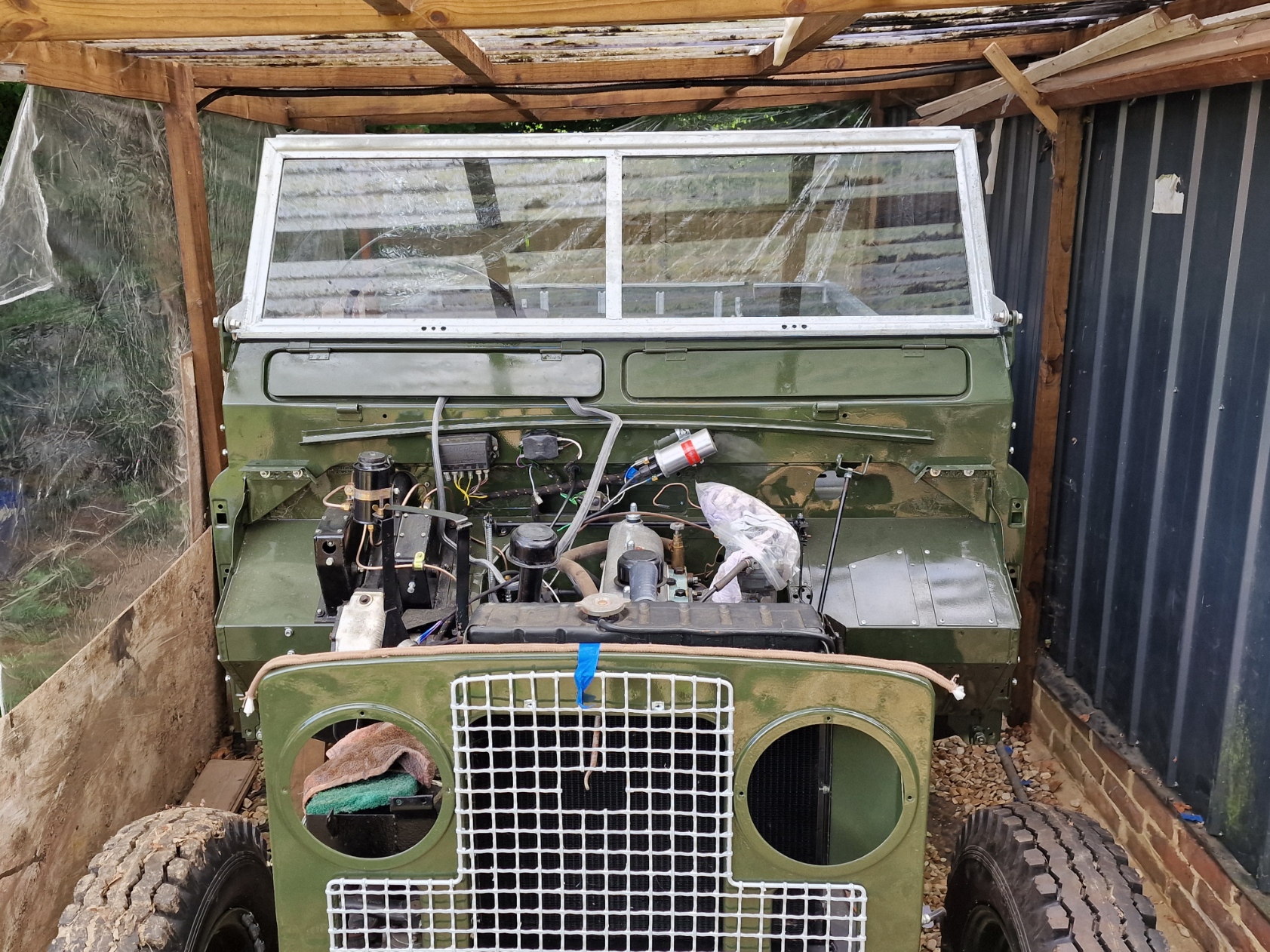
To finish the day, did something else completely unnecessary, but good to see it starting to all come together, added the windscreen and put the front grill and radiator back on, and this time plumbed it into the cooling system.