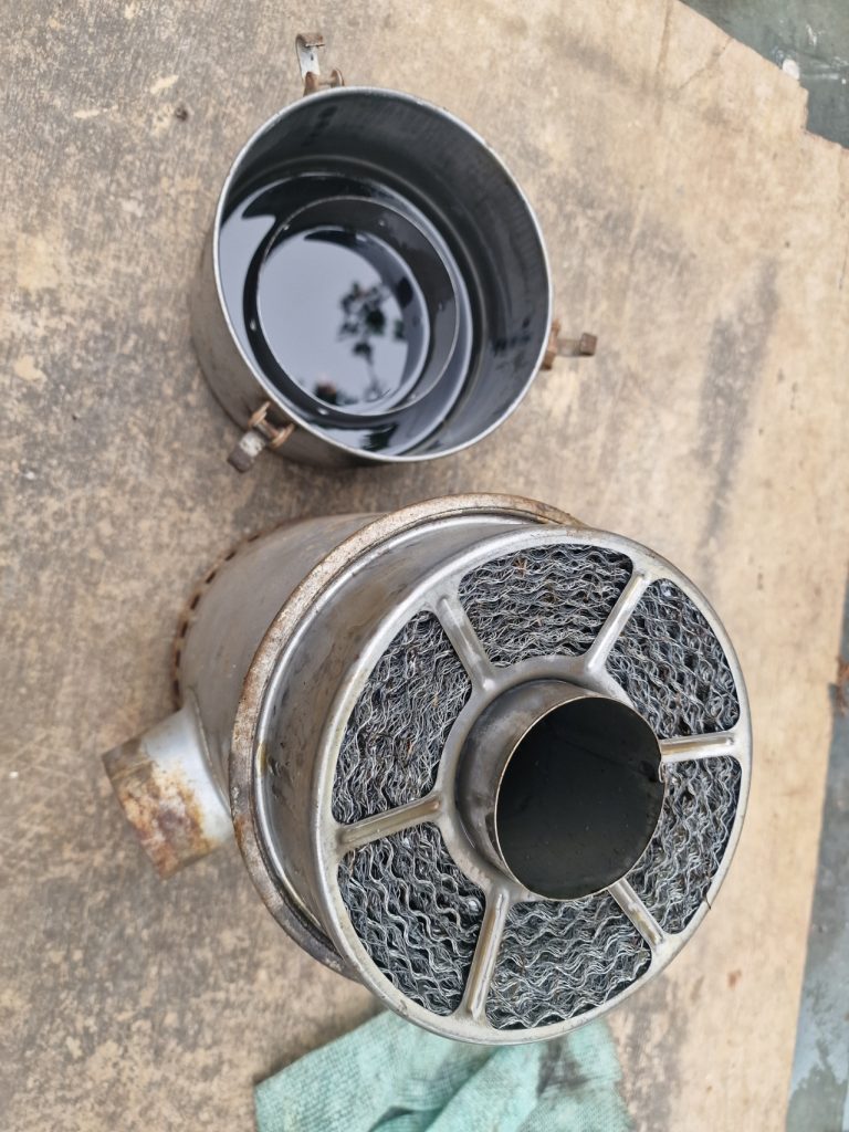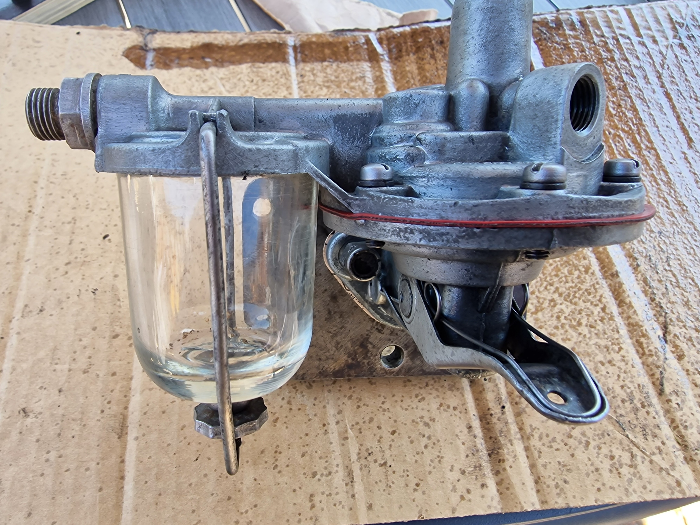
Carburettor Rebuild
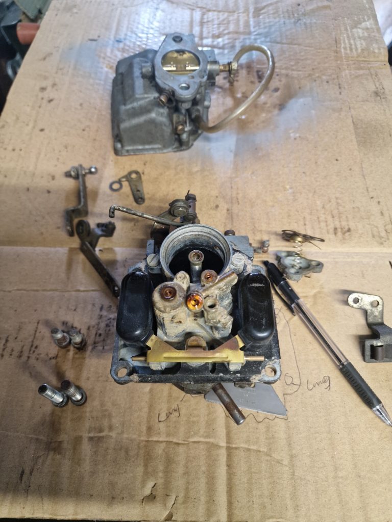
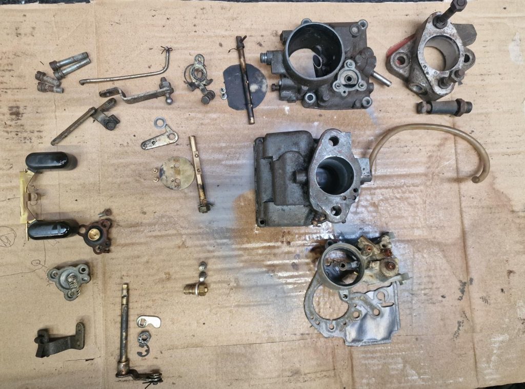
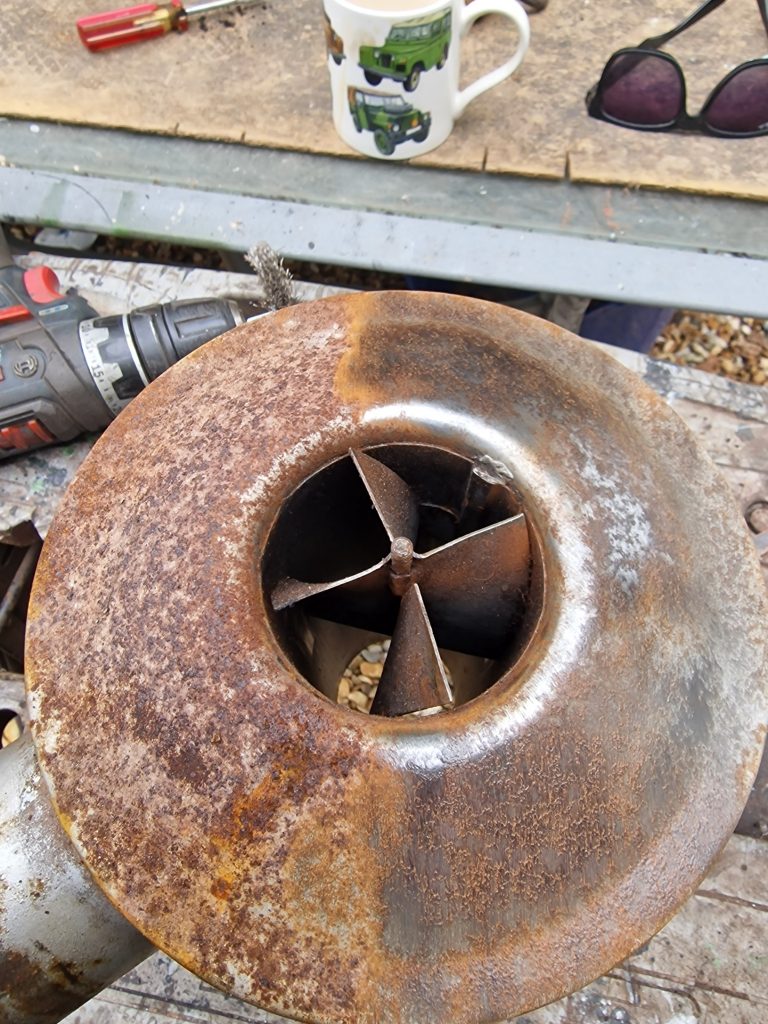
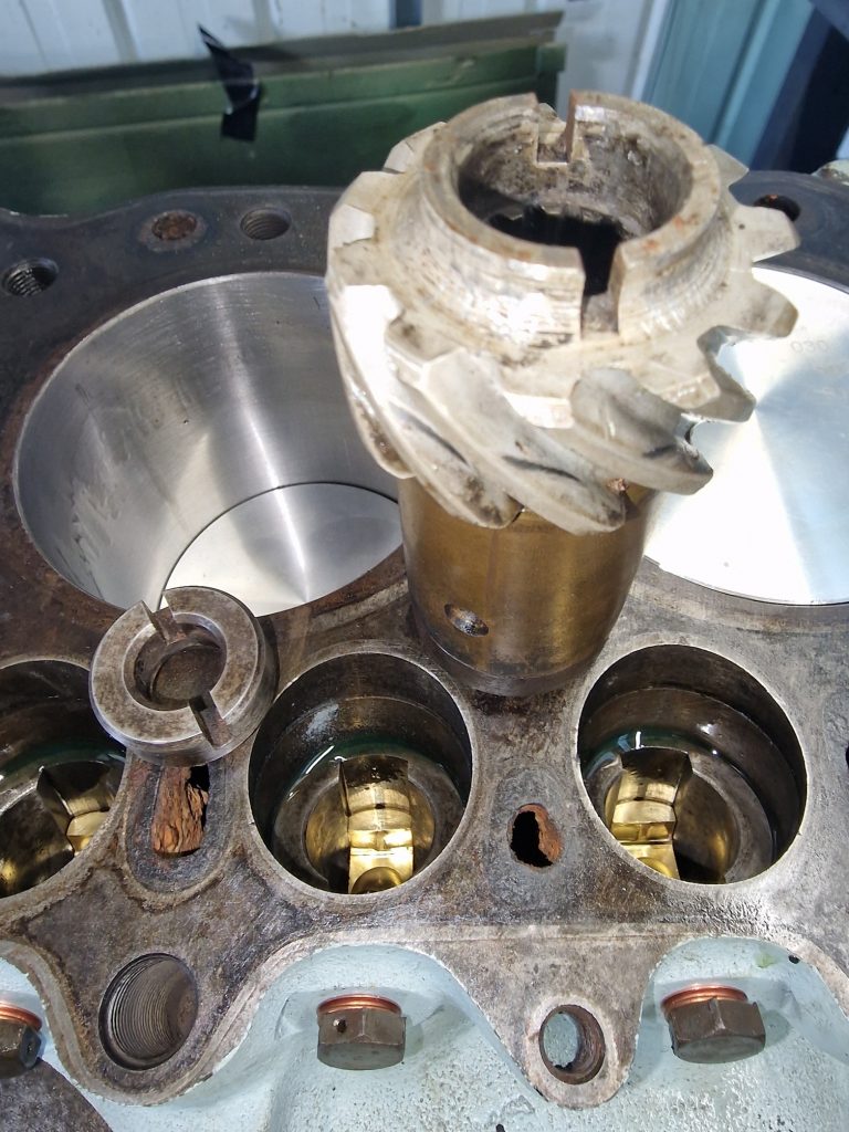
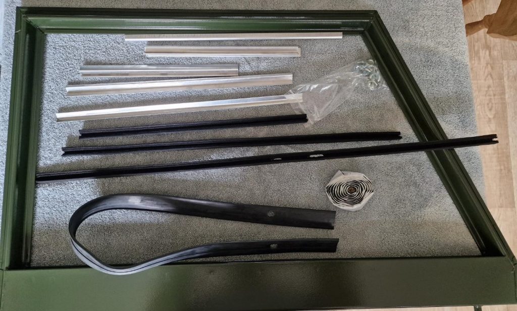
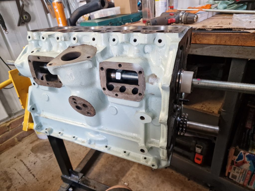
Before I start, the main picture for this post, please ignore the split pins!! the ones in the new kit I used were crap, so these will get replaced with better ones.
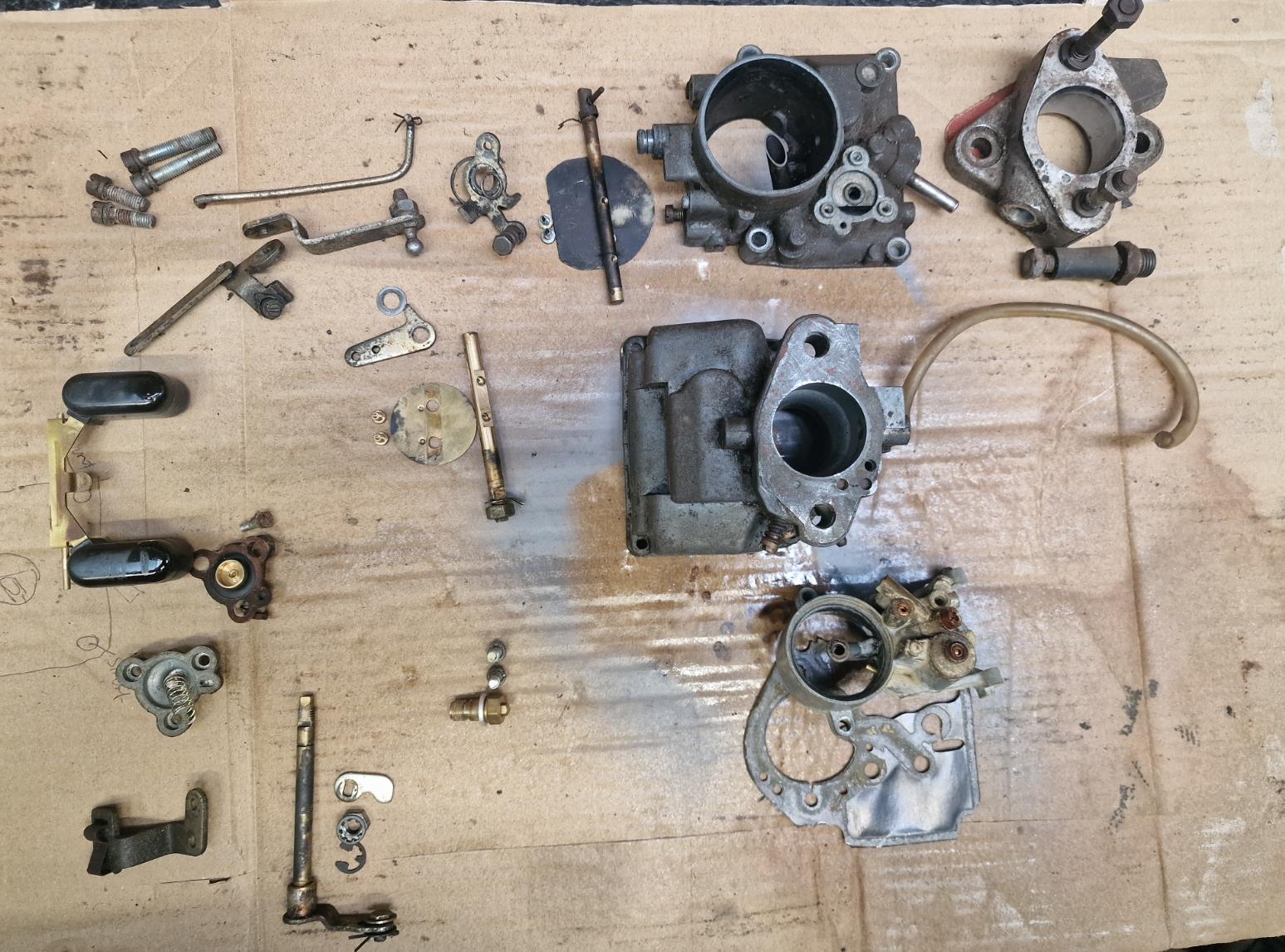
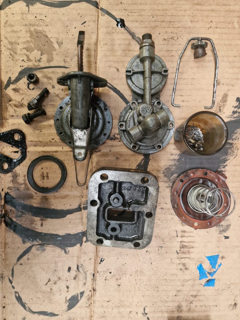
Seems things are taking an age to get finished on this Land Rover, but things are getting done, albeit sometimes 2 or 3 times over. The last update was about the Carburettor Strip down, which was pretty simple, but resulted in a pile of tiny bits.
Putting it back together, surely would be simple. I bought a carb re-build kit, which has all the bits needed to rebuild, or so I thought. So lets get to it, and not necasseraly in the order things were done.
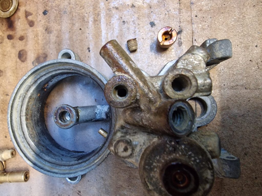
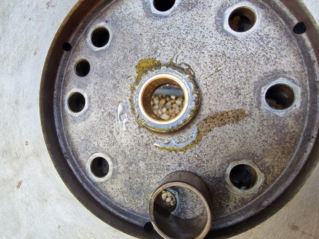
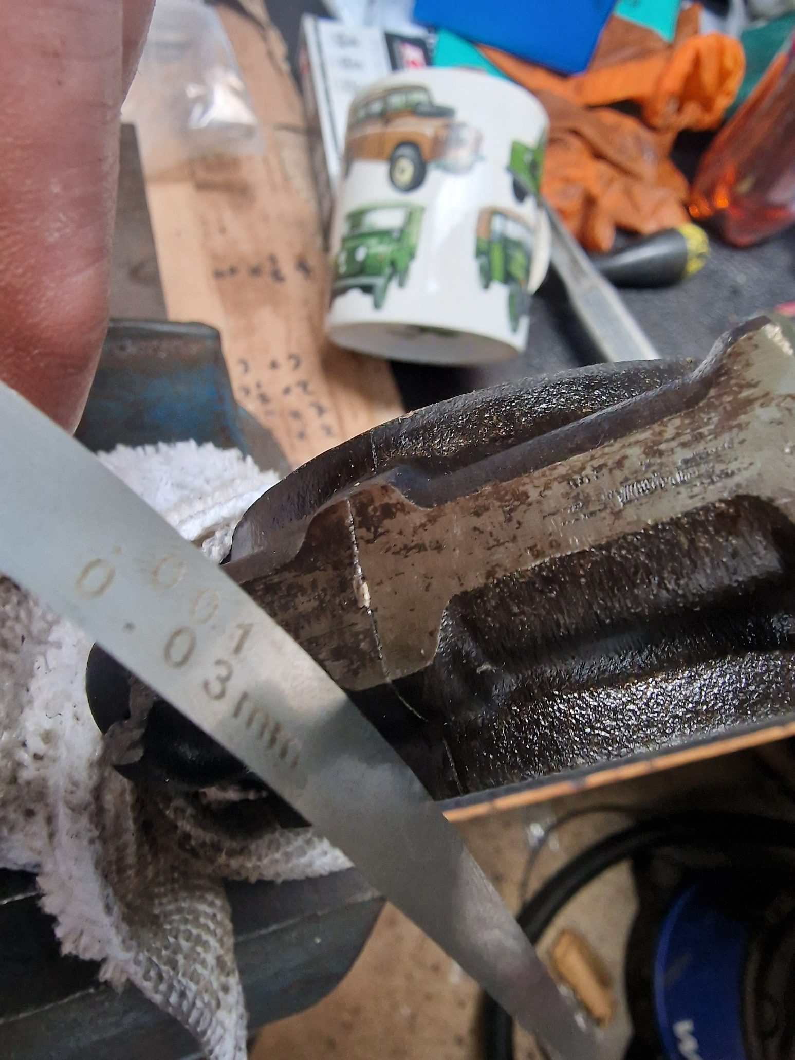
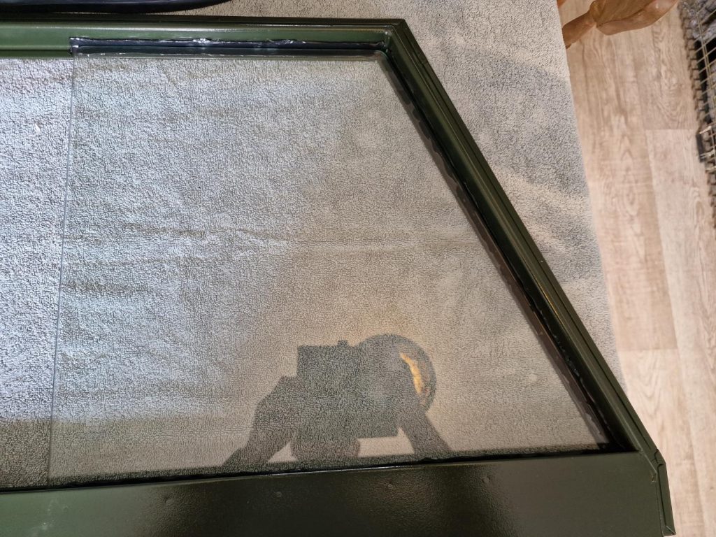
First off, the top and bottom parts are bolted together, with a gasket between them. One of the things everyone says is that these carbs over time warp.
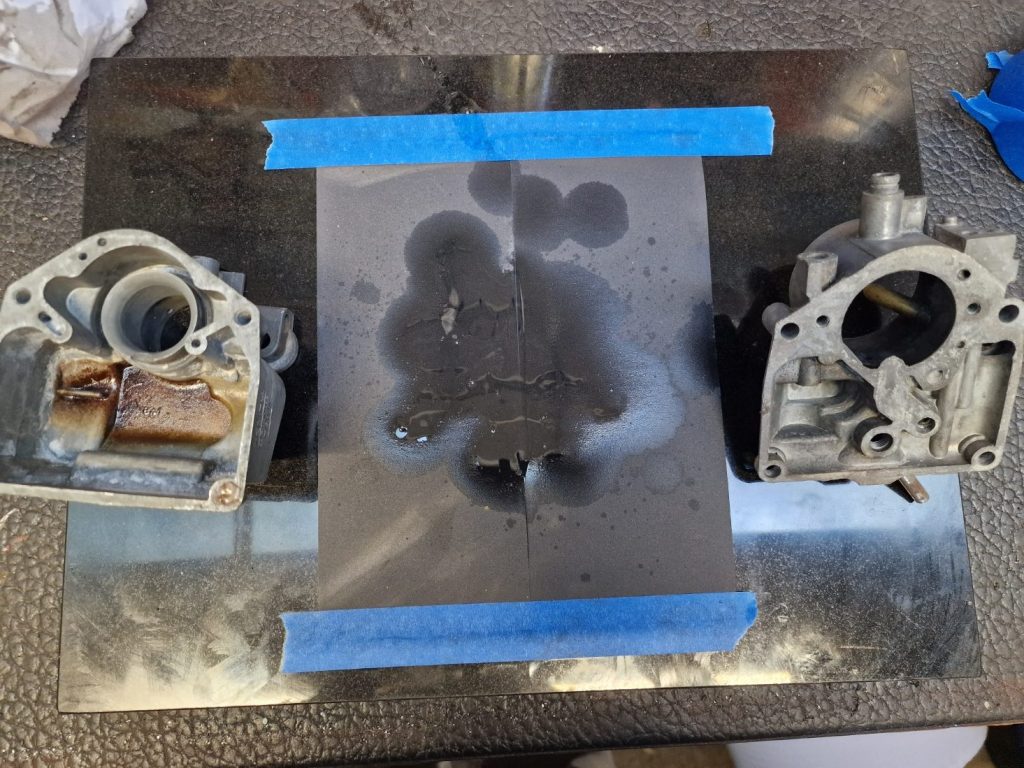
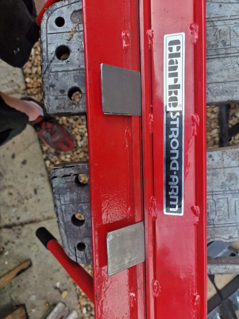
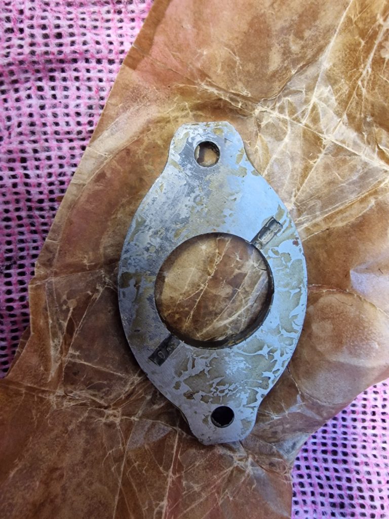
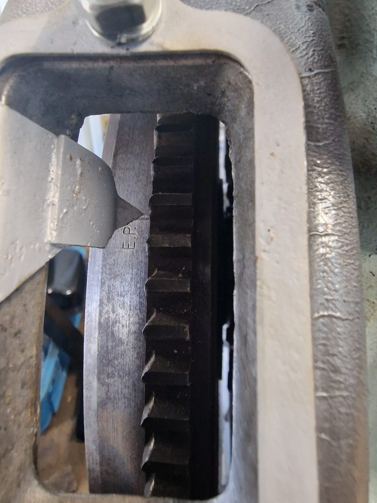
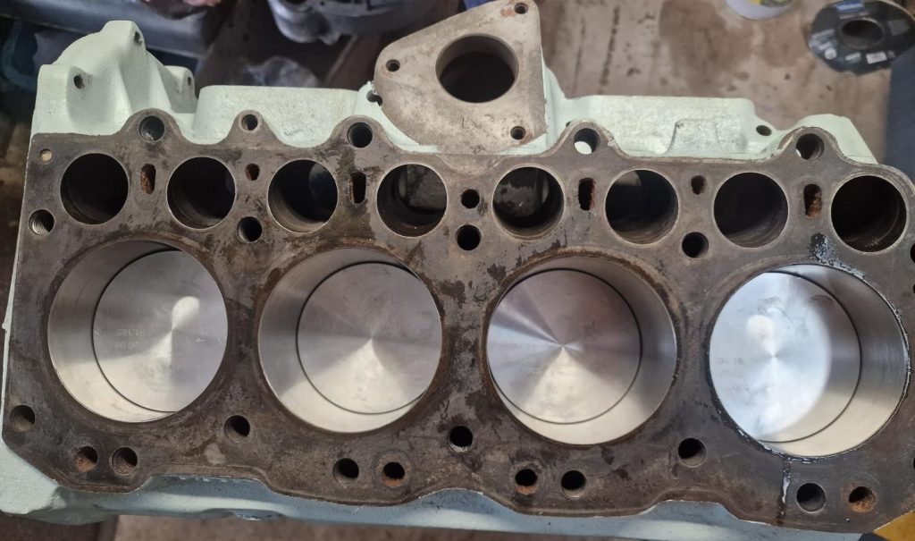
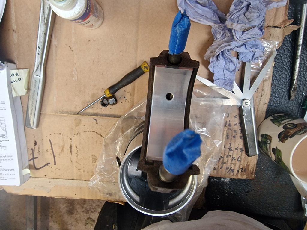
First thing was to hone the faces, until they are bright and even. I used some fine (600) grit wet and dry, with a coating of light oil and gently rubbed the faces.
Importantly, the surface was a perfectly flat piece of marble, which I hope ensures the finished faces are also perfectly flat.
I had started in this picture.
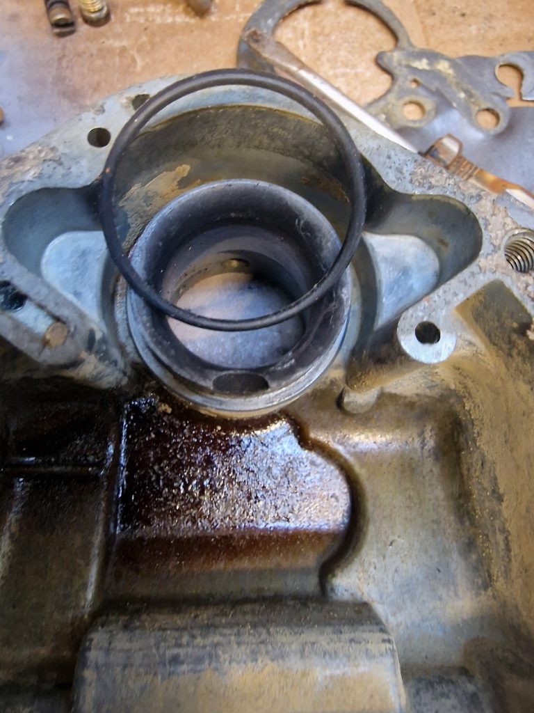
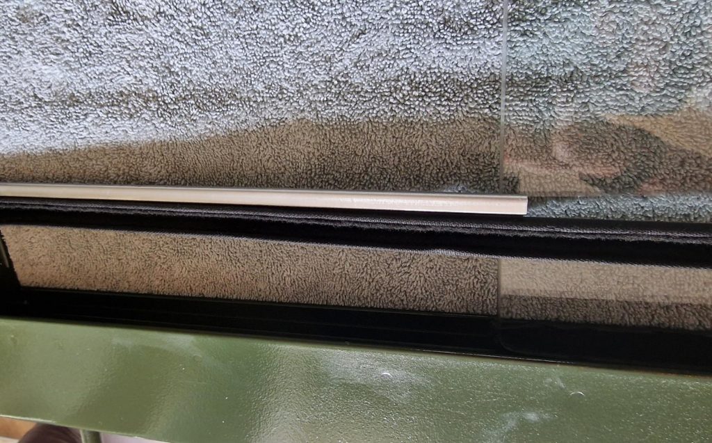
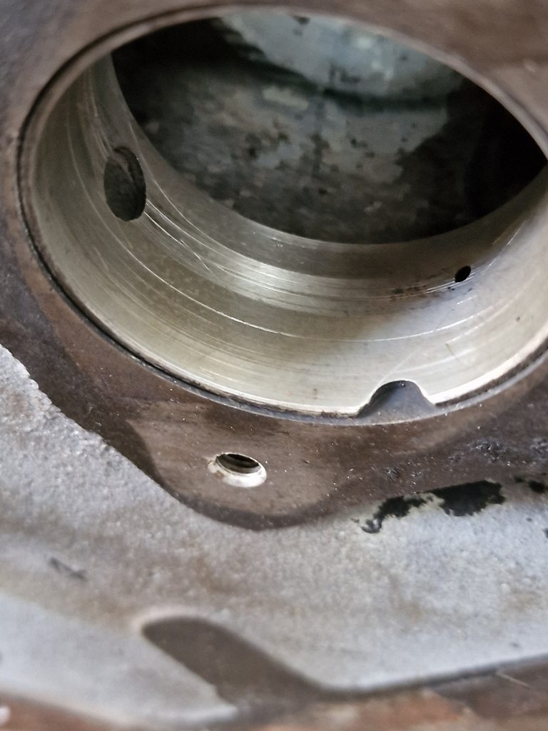
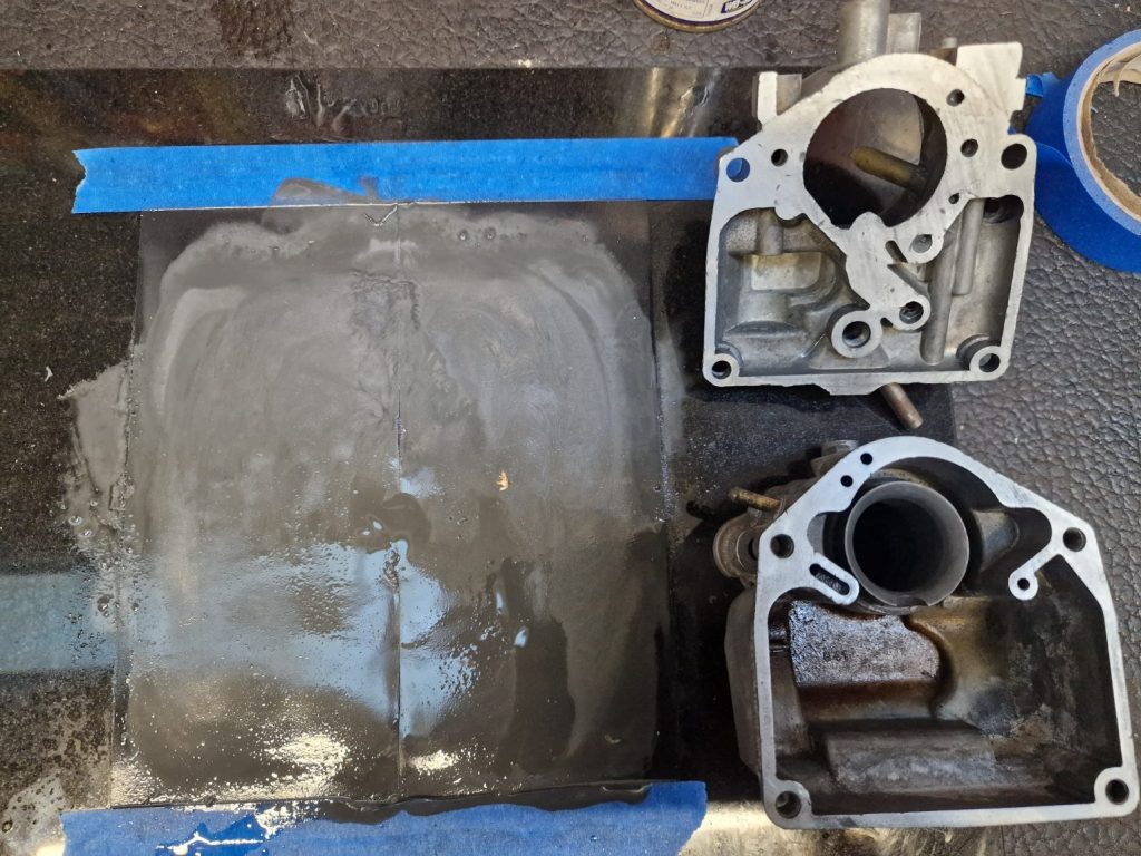
These are the finished items, nice and shiny, except for 1 small mark on the bottom case, at the very bottom.
It feels very flat, and didnt want to keep going on this one mark.
The issue with them not being flat, is that they can let air in. Not good in a carb where the whole idea is to get the perfect Fuel / Air mixture.
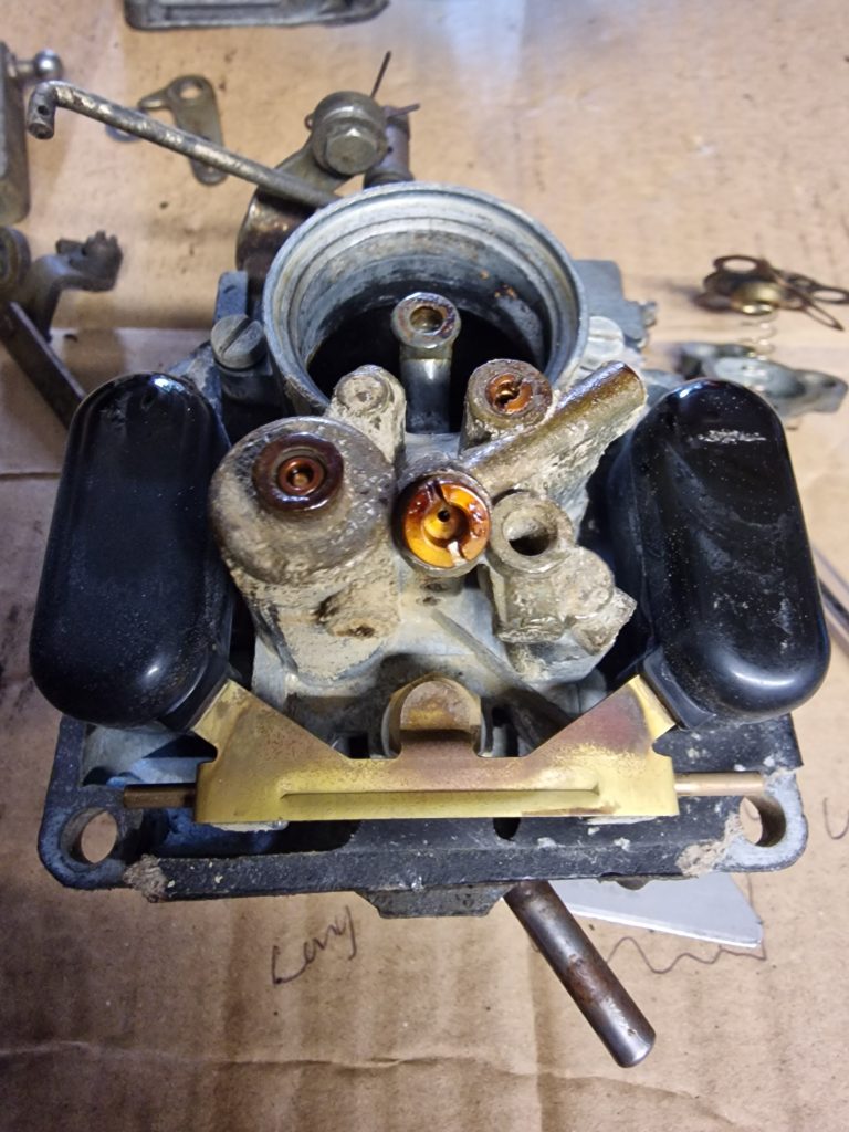
Next was to start putting back all the new jets and bits and pieces. There are a few of these and one of them had me stumped for some time as I could’nt remember where it went.
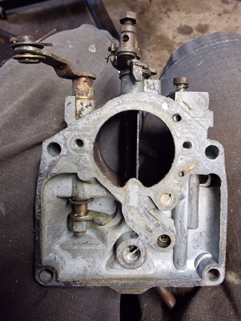

Now you might be thinking, some of those bits look a little old. Well, they are, the kit as it happens does not have all the bits in, so ended up using some of the old bits as well as new!
Also, one of the videos I watched on rebuilding a Zenith 361V carb, suggested that the main needle valve replacement had a nylon tip, where the original was all brass. That was indeed the case, so as in the video, I chose to use the all brass version, as it didn’t look worn at all.
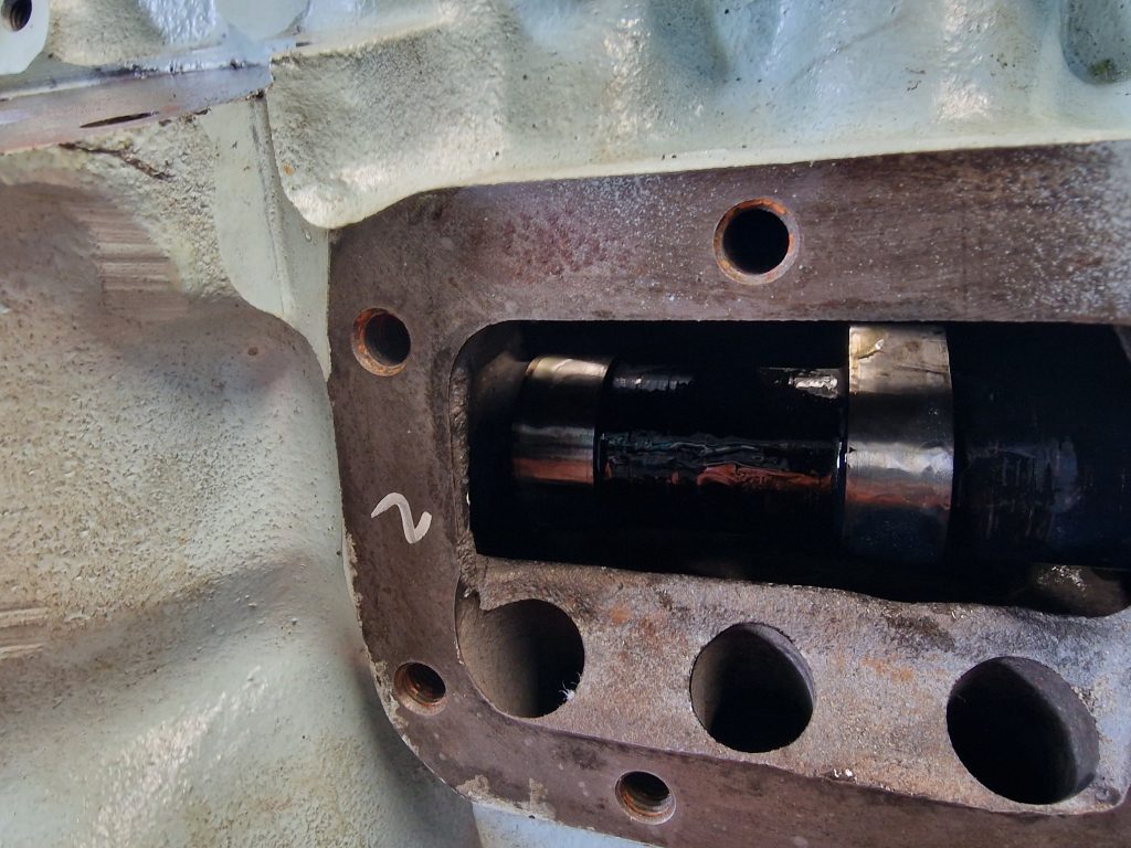
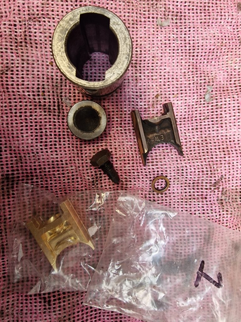
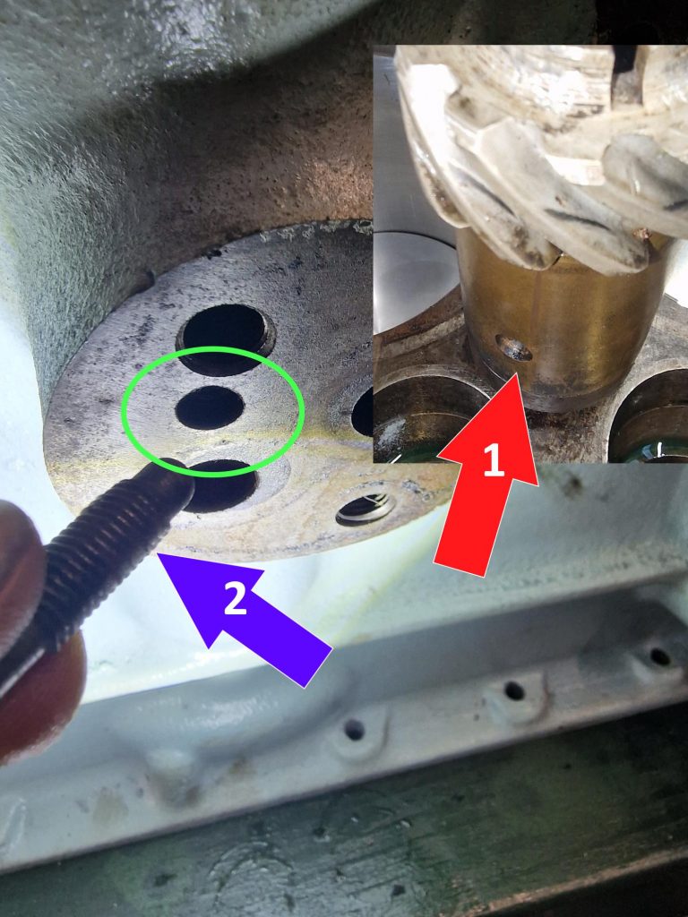
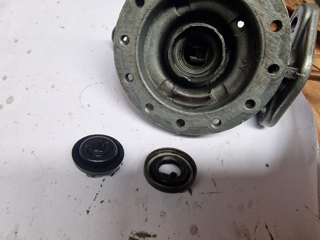
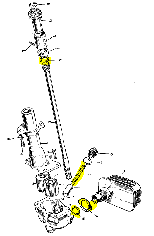
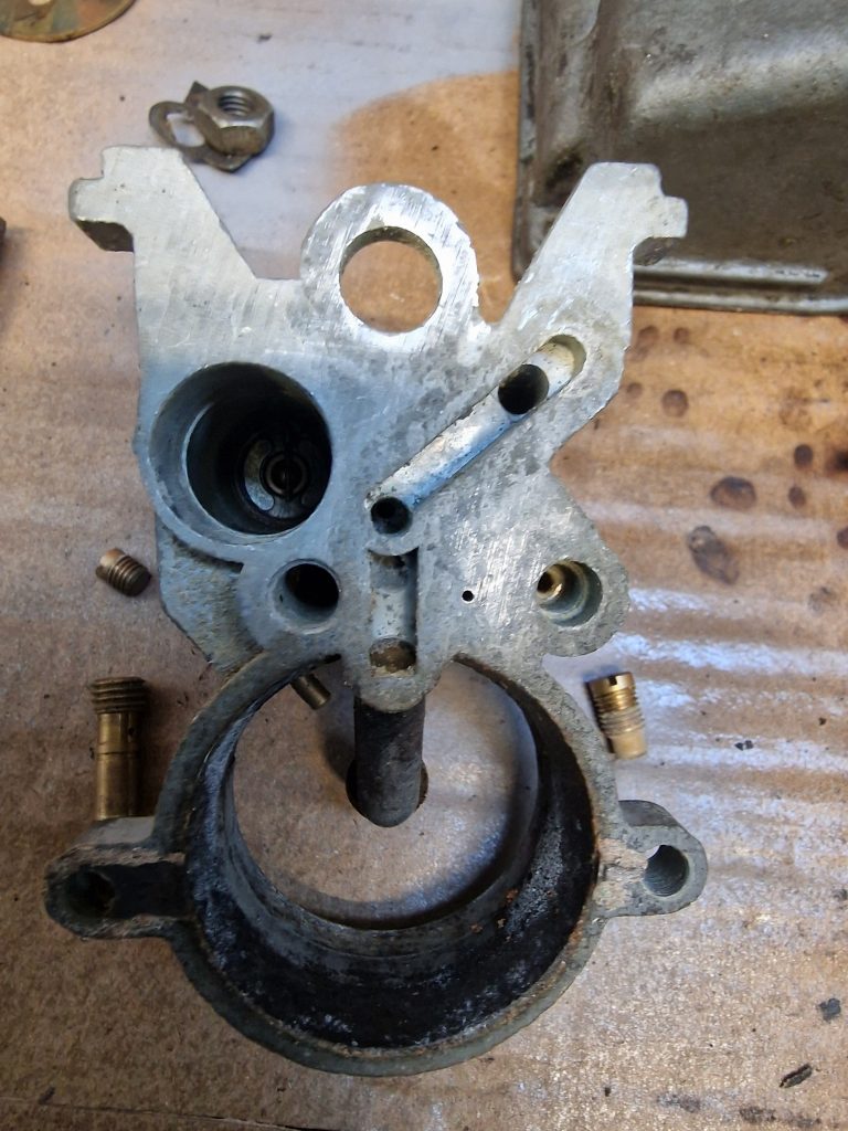
All jets back in, start to assemble the case, but before we get to that, I had one little problem. I managed to loose 2 pieces (circled in the images below).
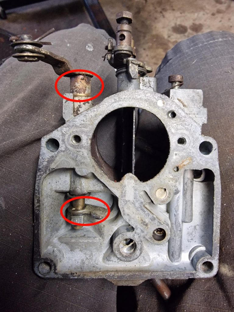
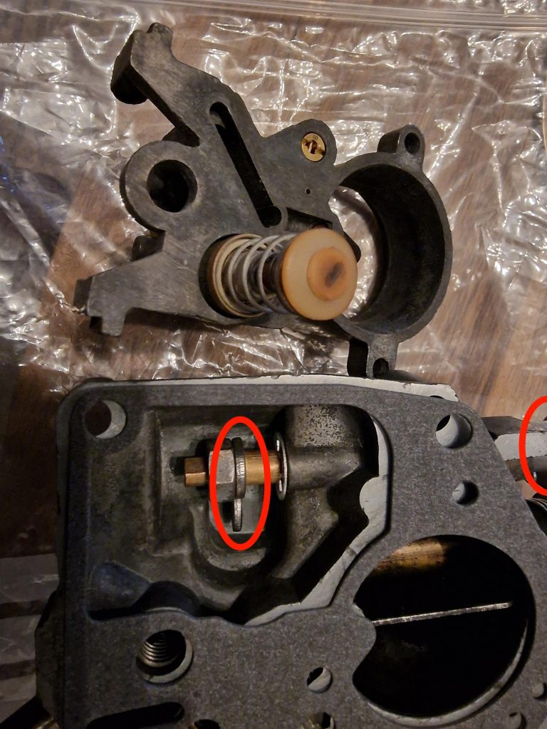
The one at the top (not seen in this smaller picture) is just a simple spacer, the one at the bottom is the arm that pushes the piston for the accelorator pump.
It is this bar that is connected to the accelorator peddle, so when you press down on the peddle, hopefully this results in more fuel into the carb, leading to more speed (or not, given its a Land Rover)
Anyway, I nearly went off and bought a second carb, just for these two bits, just about to buy it off FB marketplace, when I thought, just one more look… and amazingly, it was the first bag I picked up, and there they were. Phew..
Ok, so onto assembly, pretty simple, so nothing much to say or show about that.
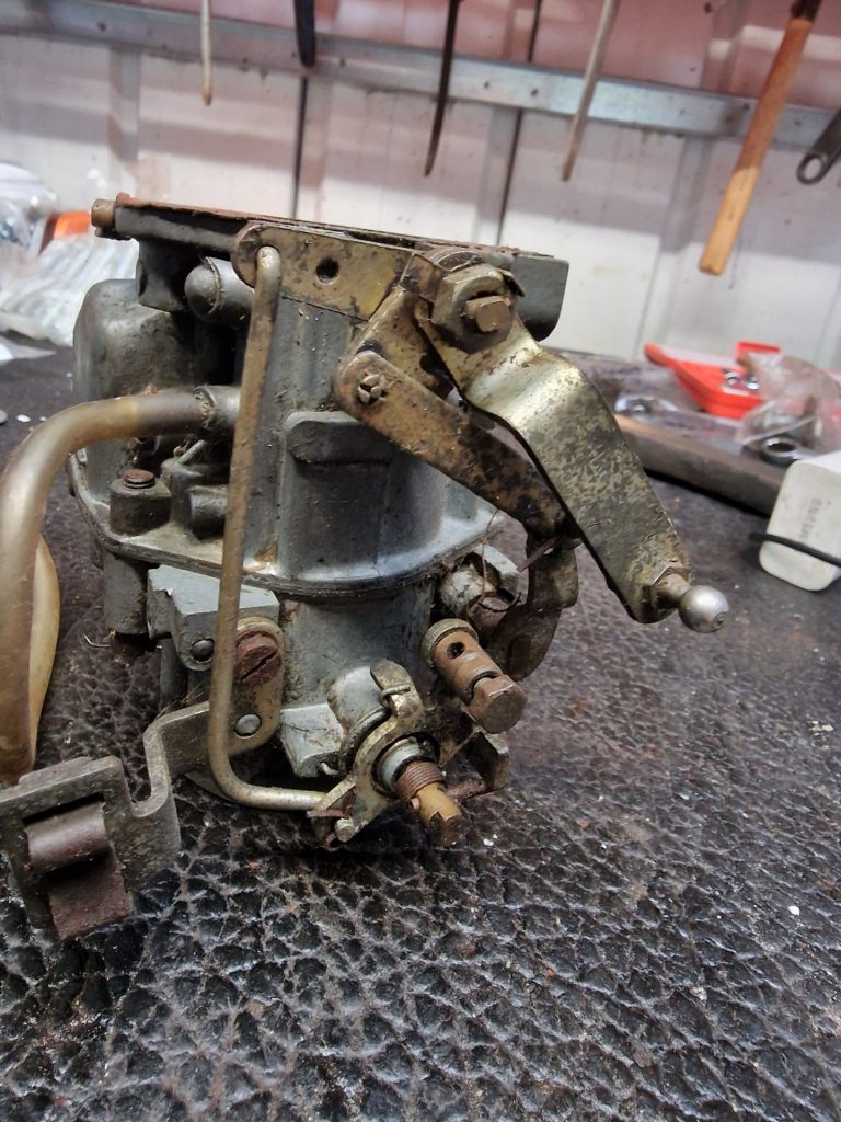
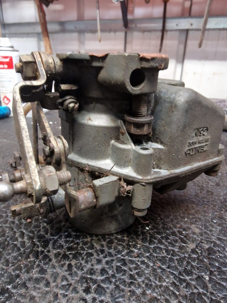
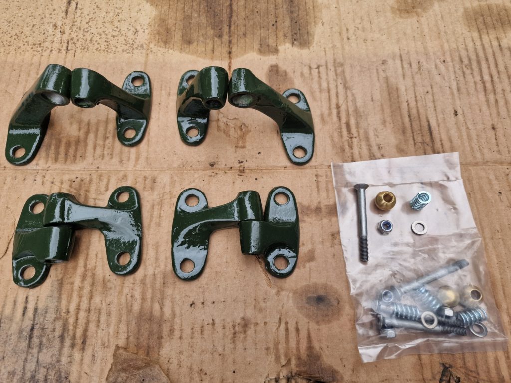
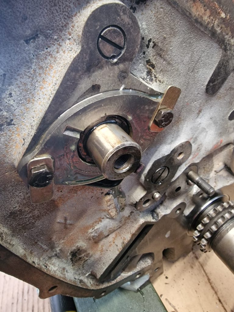
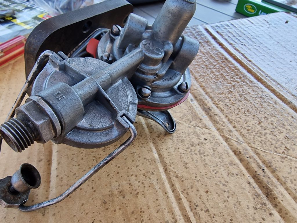
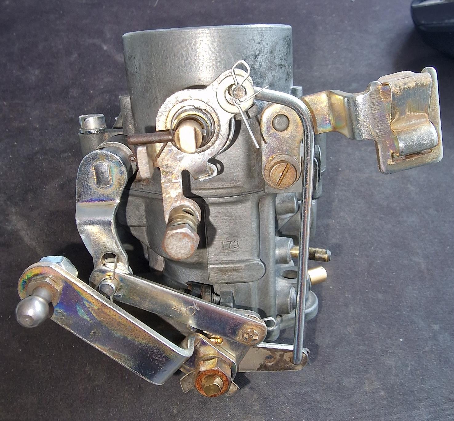
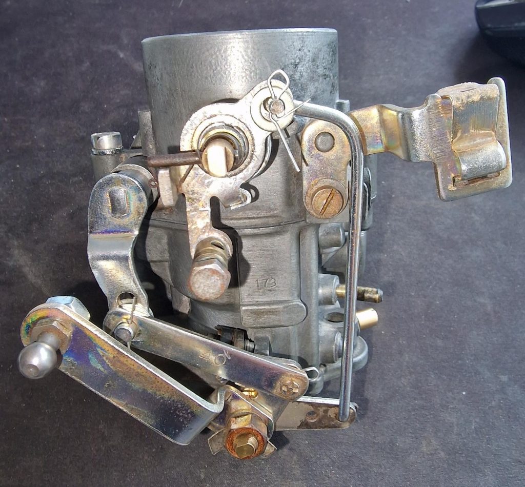
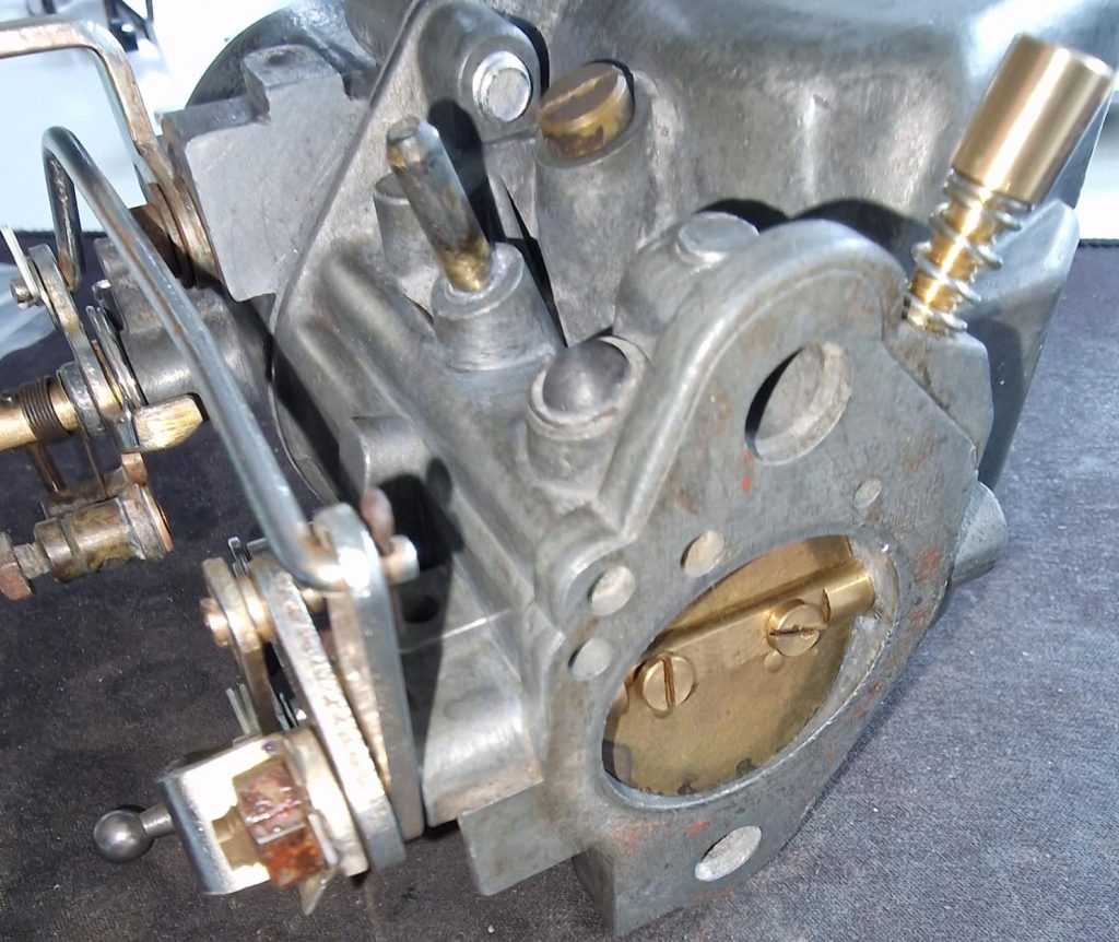
The next part then was to put all the the levers on, which had me turning it upside down, back to front to try and figure out how they all fit. One thing I did do was to get my Zinc plating kit out again, and this time used both Silver and Gold/Yellow passivates, with mixed success, but certianly better than putting back on crusty / rusty parts. Simple lesson if Zinc plating, Clean, Clean and Clean again, without which you wont get good results.
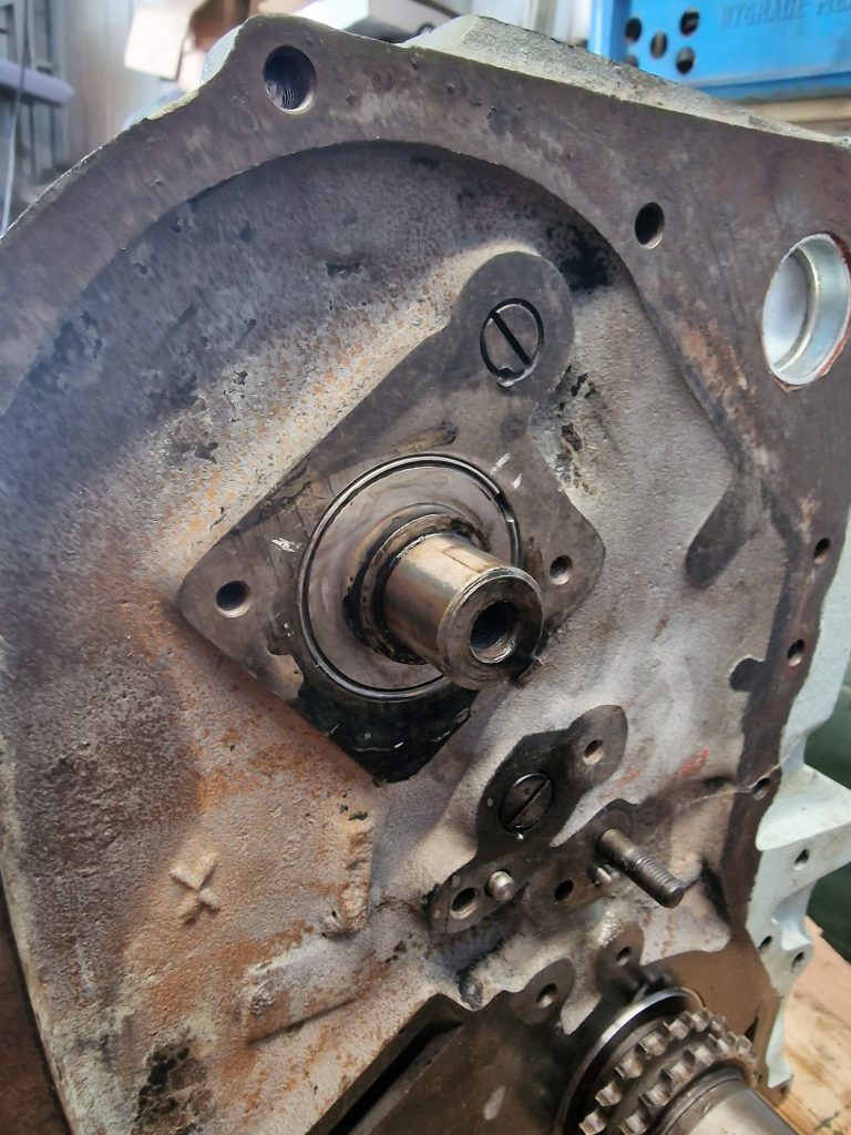
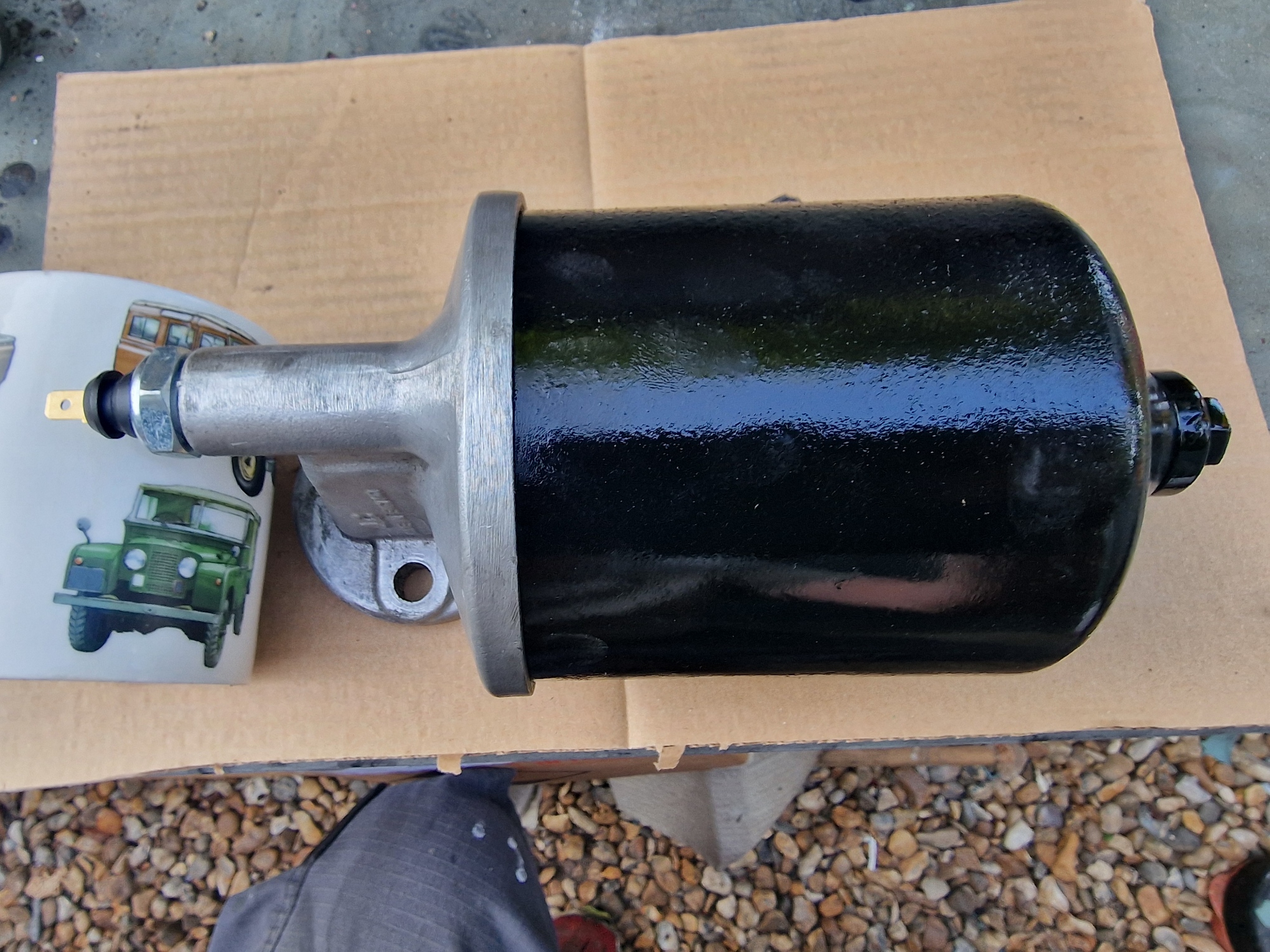
These three images, 1st one, before, 2nd and 3rd images are after. While not perfect, I think they look the part.

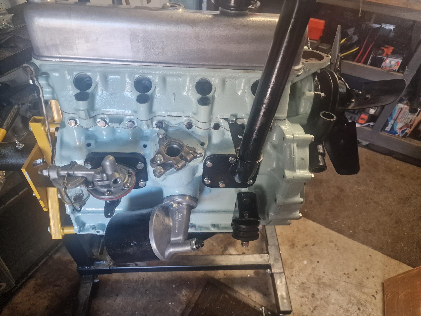
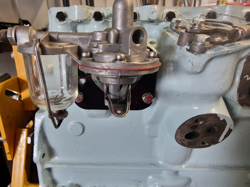
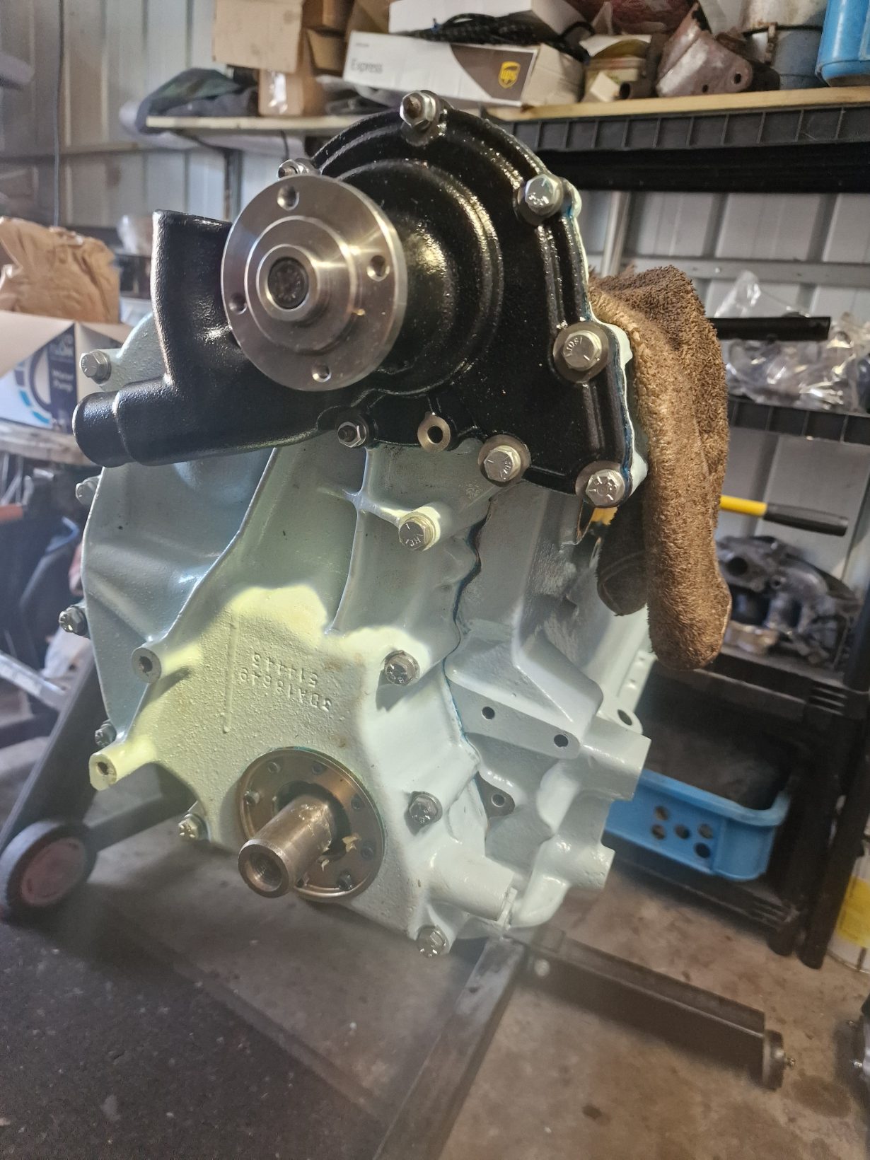
All that remains with this is to put it onto the engine. Now, that leads me to another topic, that I’ll touch on here.
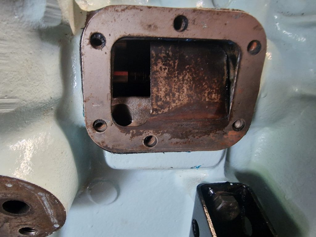
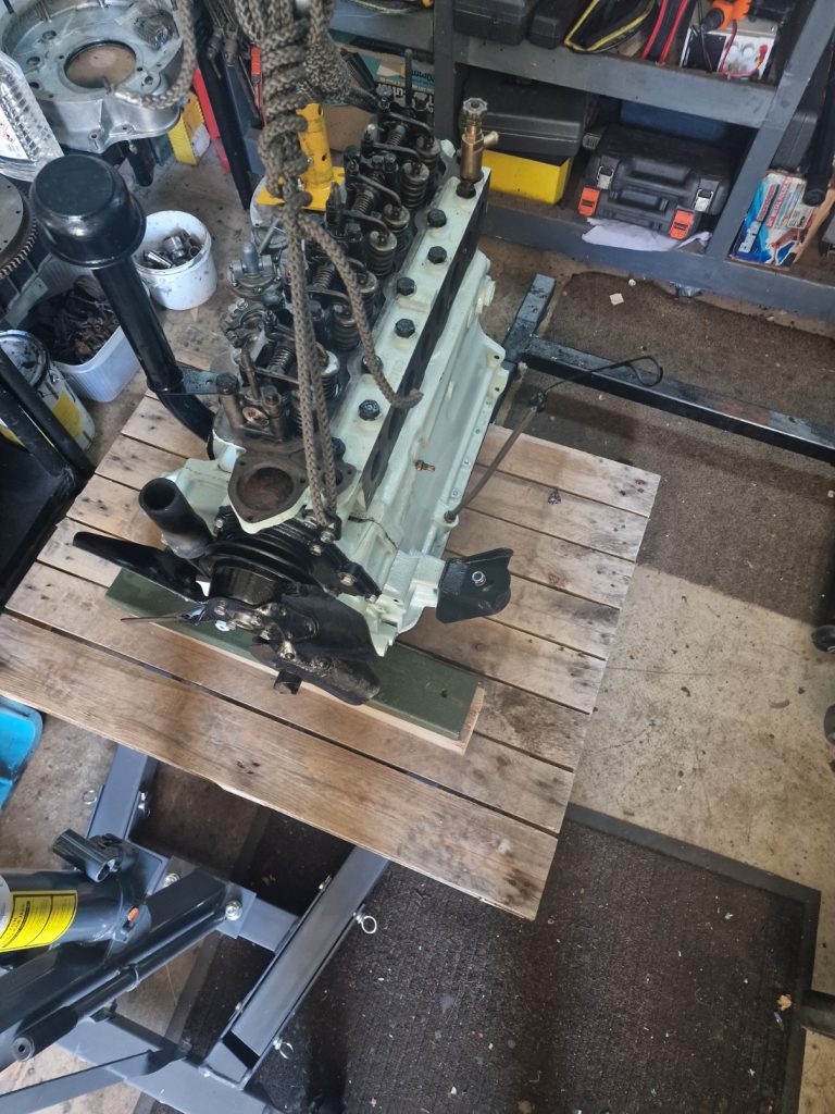
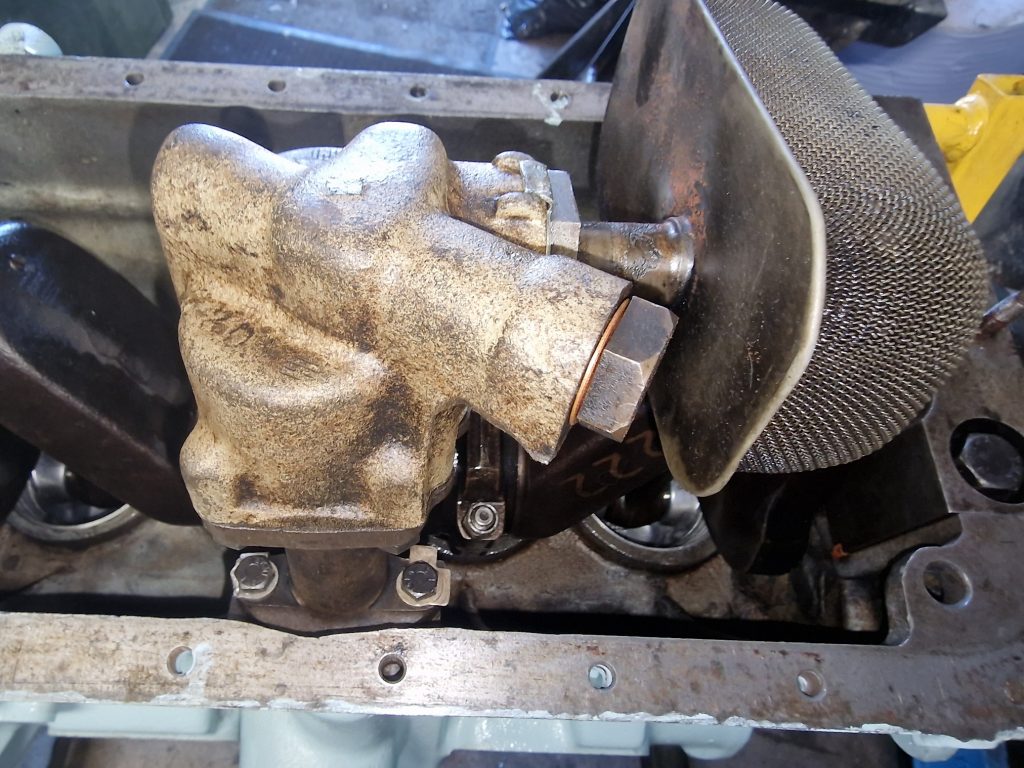
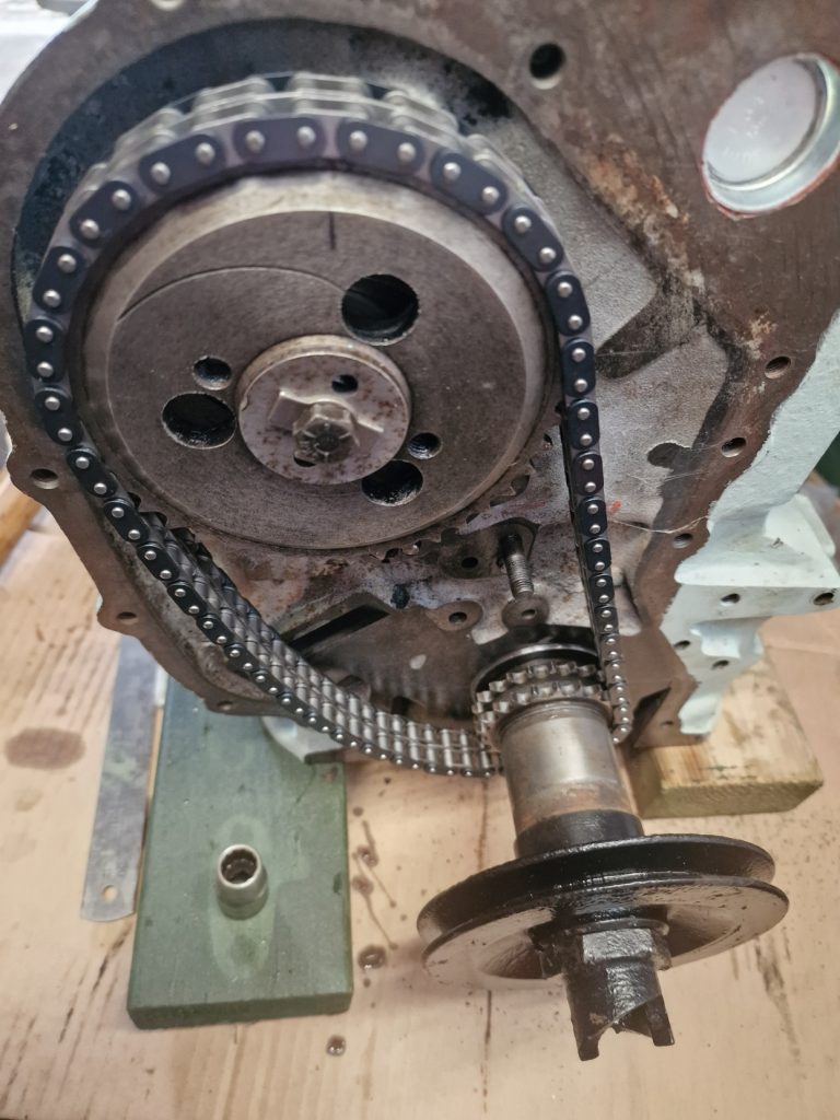
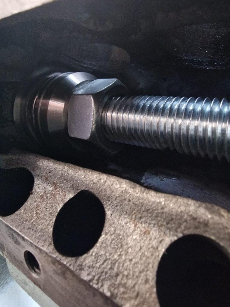
I had a weekend a couple of weeks ago, where it seemed everyhting I touched turned to SH.T. Very briefly, I put new studs into the head, to hold on the manifolds. Stupidly, I tried to put them in the wrong way round, should have been short threaded end into the head, so ended up buggering those up. Replaced them with Bolts, all good, they tightened up nicely, so went on to Tighten the 4 nuts holding the inlet manifold onto the Exhaust manifold. The reason for talking about this here, is because the carb sits on top of the Inlet manifold.
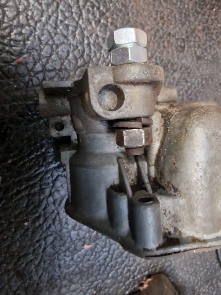
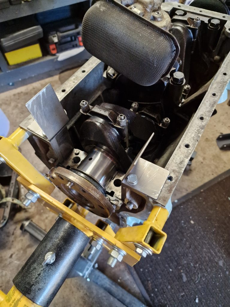
Anyway, only needed 17ft lb torque, 1 OK, 2, OK, 3 OK, 4, Humm, doesnt seem to be tightening. SNAP, the f’ing stud snapped.
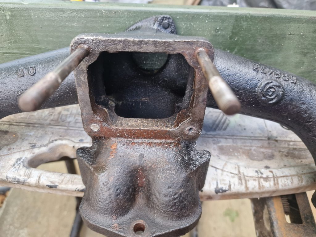
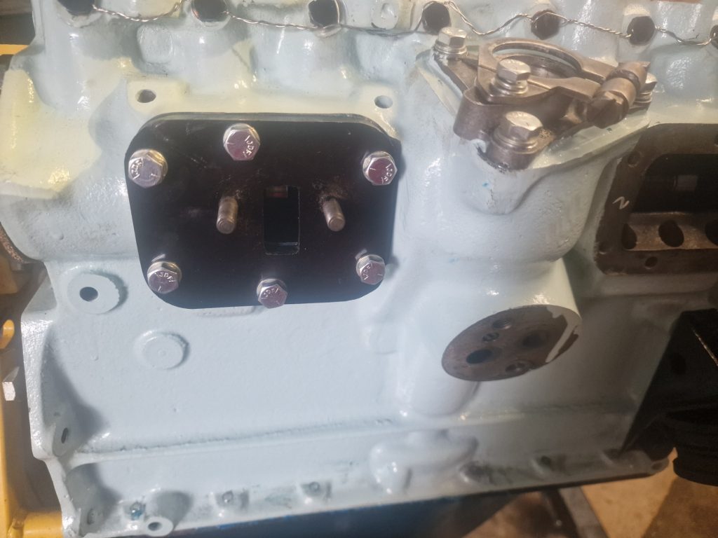
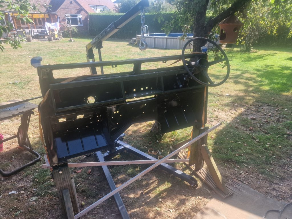
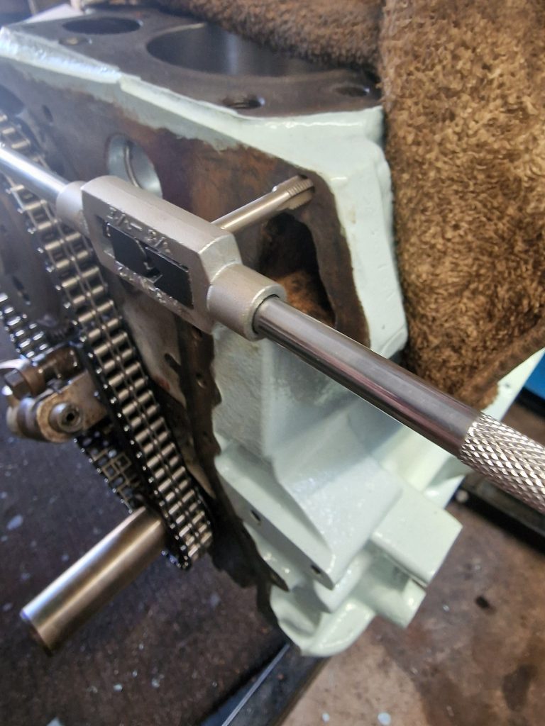
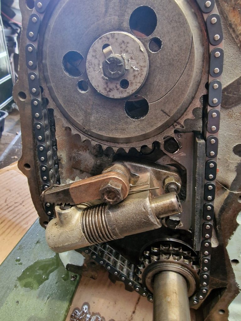
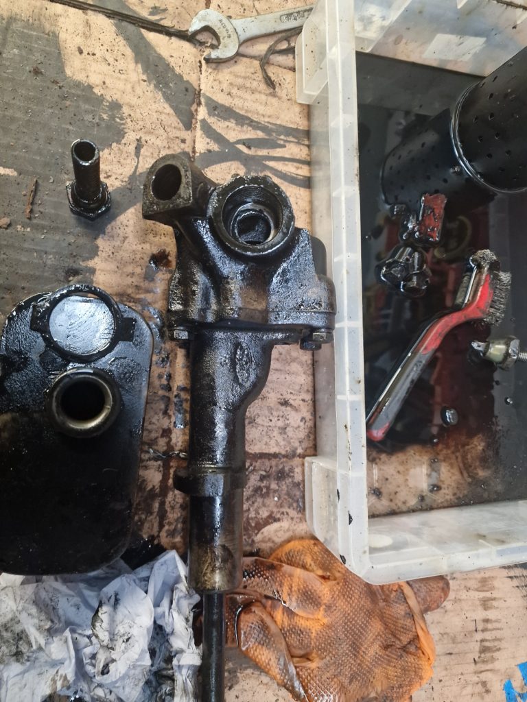
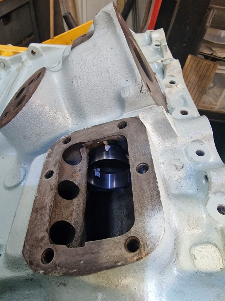
This pic is after I really did throw my toys out of the pram, after which I calmed down, partialy, well enough to pick up a hacksaw as I decided the only way forward would be to cut them all off, drill them out and re-tap the holes.
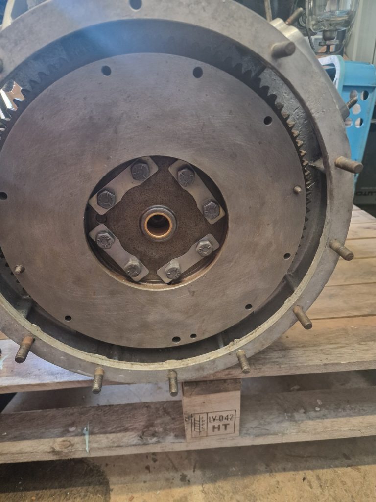
Did a fairly good job on the pillar drill, not 100% straight, but good enough. Put new Studs in, 1, good, 2, good, 3 good 4, bugger it stripped the new thread, Ohhhh, FFS.
The moral of the story, leave jobs like this to the pro’s. Ended up buying a new Exhaust manifold, and more new studs for this and also for the head.
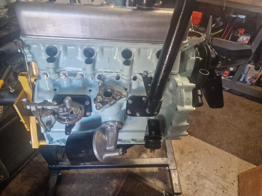
So, after all that, kindoff back on track now, (certainly in terms of my thinking) with a revised plan, so will crack on with finishing off the engine in the chassis on the next dry weekend. Until then….