Well, I did say I would move away from Topics, to thigs as they happen, and this is a true example of that with a real mix of topics covered.
So to keep it in some order, I might just link to other pages, for the detail
Propshafts continued…
Whats up first? Well, how about prop shafts. If you look back at a previous post December 2025 I mentioned the work on my propshafts, namely trying to put in new Universal Joints, which, was a bit of a disaster. None of the three I did were anywhere near god enough, they were all super tight.
So, I bought myself 3 new UJ’s, and set about a little more research. I found a video by someone who I have watched before, and it kind of gave me some “oh, I could try that moments” so I did.
Heres the video, by Steamwally
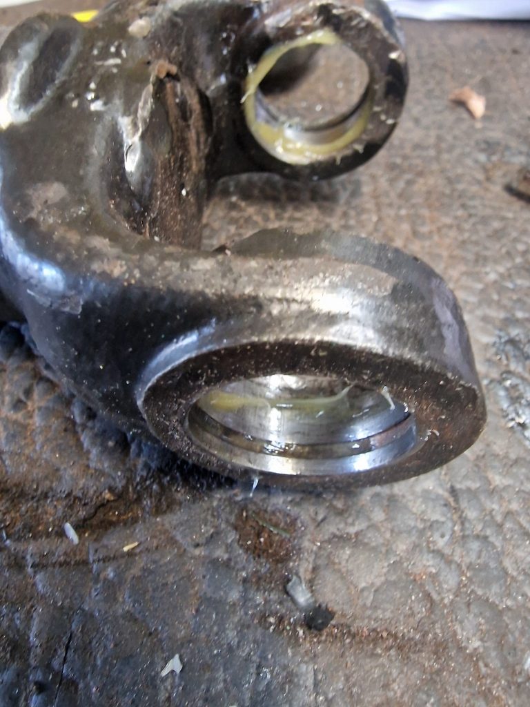
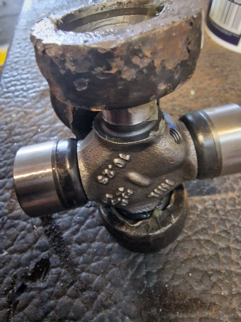
First thing, was to really spend some time cleaning the journals (or whatever they are called), I did clean them last time, but not enough. Also, I made sure the circlip grooves were really clean.
Before trying to insert the bearing caps, I also applied a little grease, to help the bearing cases in.
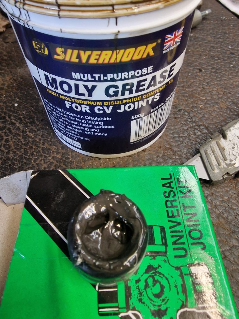
Second, which I probably should have done the first time around was to fill, about 50% of the bearing cap with moly grease. Taking care of course to make sure that none of the roller bearings come out.
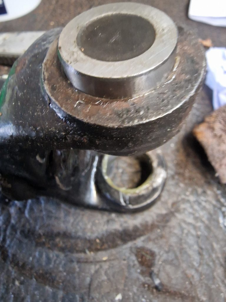
I then gently positioned the bearing cap in the journal, and pressed it half way home.
Now here’s the difference from last time. Last time it took considerable effort to get these caps in, this time, it took only gentle taps to get the in.
Ignore the hammer marks on the journal I do appreciate that this has probably un-balanced the prop shafts, but this is how bad it was getting the last lot in and then out again.
Anyway, With the 1 cap in, the UJ was positioned, and then the other cap positioned in the other side. Gently tapping in, until the Circlip would sit in the grove.
To finish off, a couple were a little tight. but as I learned from others, give the prop a gentle tap to make sure it settles in and it should be OK. And guess what, they all were, all are not loose, but certainly not super tight either.
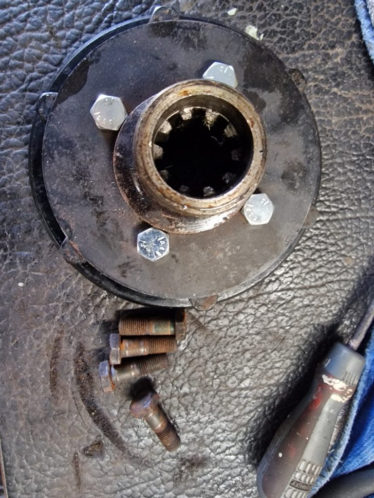
When I bought the first set of UJ’s, I also purchased new prop shaft bolts.
To get these in, I had to take off the back of the transfer box, to get the new bolts in, as they are in-accessible when its all together.
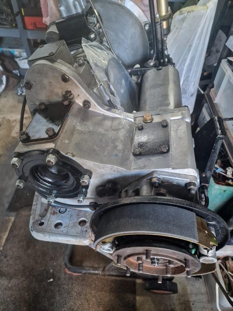
You can see this part towards the bottom of this picture.
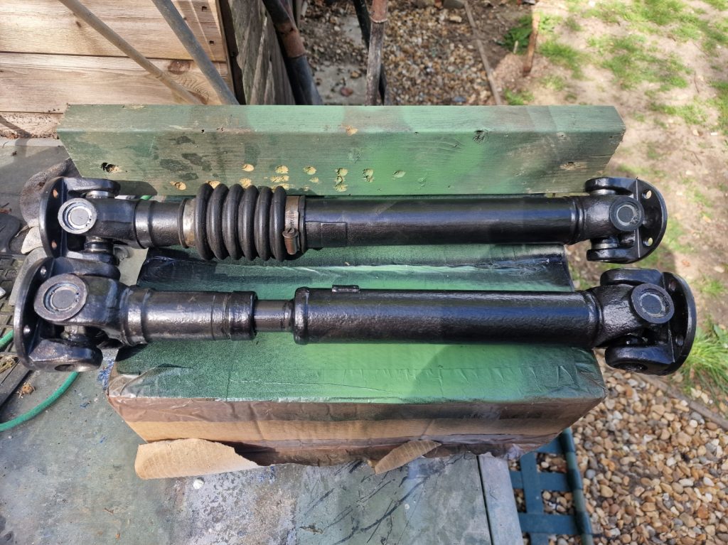
Here’s the finished prop’s ready to get bolted on.
Petrol Tank – re-visited
Something else hanging around was the petrol tank. My painting was not great first time around, so had taken it out cleaned it up and re-painted it again. But more importantly I had tried to save the petrol sender, the bit that shows me how much fuel is in the tank If you think about your toilet, its a little like the bit in the systern, its a floaty thing, that goes up and down with the petrol, sending a signal to the petrol guage. Anyway, the original one was not reliable so I bought a replacement.
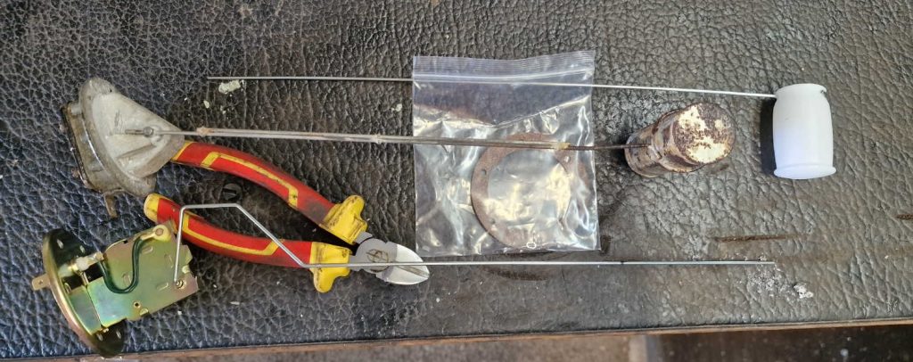
The old one is in the middle, and as yo can see the new one is in two parts. These have to be connected, giving the same length as the old one.
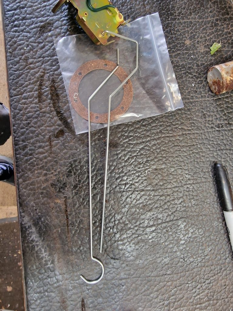
I cut the bar connected to the sender unit first, and then making sure the length was the same, started to firm the other bar, so that it was not simply laid along side and connected.
I feel sure that adding some bends, will stop it twisting when its in the Tank.
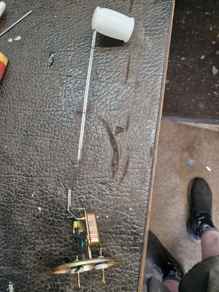
I then connected them with some little clips supplied, and then went on to solder them together.
It felt pretty strong, so see no reason to doubt it will work as expected.
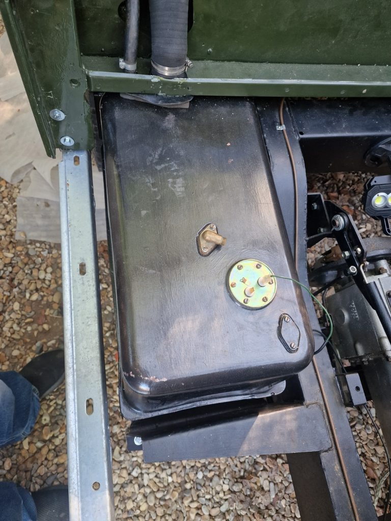
I thought the obvious thing was to put the tank back into the chassis, as it went in last time trouble free, that was without the rea tub on, now the rear tub is on, the neck of the fuel tank needs to come up through a hole in the tub. Now this is where I got really pissed off, it the neck of the tank would not go through the hole, it looked like the tub was too far back, but it cant be! its attached to the rear cross member, so can only be where it needs to be! Nope, it wold not go, so in my frustration took my hacksaw out, and cut away part of the tub, to make the hole a little larger, and elongated. Anyway, its not back in, and with the pipes on.
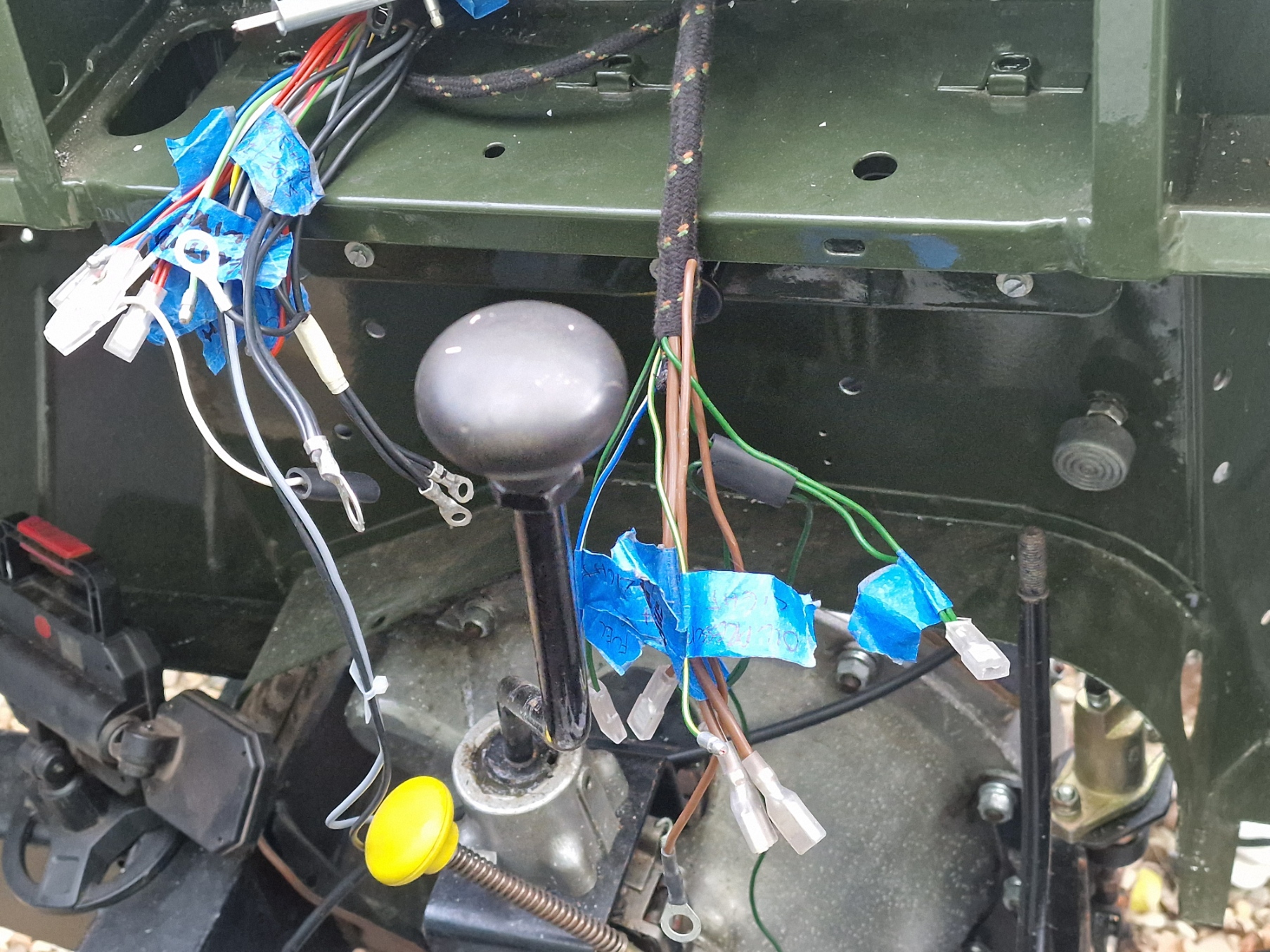
Electrics
I had done a little bit of this before, but thought, now’s the time to start fitting the harness (or loom) whichever term you want to use. I fitted the Voltage regulator, fuse box (for what it is!) and coil before, so obvious next step, feed the harness through the two holes in the bulkhead. Easy Hu! especially as I bought a rather expensive EXACT replica of a 1965 series 2a bulkhead, well no. One hole was perfect, the second, there is no way the loom will go through that! So I went to my old bulkhead to check, ands sure enough, 1 hole is larger than the other. So the bulkhead is not exact…. and what really pissed me off again, I had to enlarge the hole, ruining the e-coat, and exposing bare metal. I did paint the hole (well not the hole, thats impossible, the edge of the new hole!).
I will write this up a bit more in detail, as I have seen so many posts on various forums about asking questions about installing a Auto Sparks Harness, and I think I have it pretty much mastered.
Anyway, here’s a couple of pictures of where it is so far, and then after the pictures another little bitch.
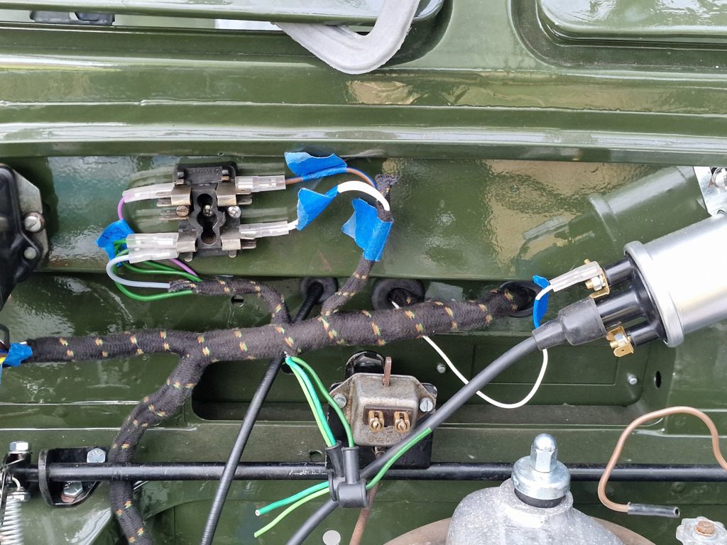
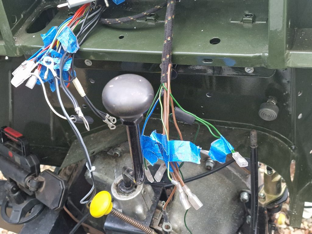
On the left, view from the engine bay, on the right view from inside the cab. Even for a simple thing like a land rover, plenty of wires to figure out where they all go. So far have all sorted apart from 2!!
Right, so I said after the image another bitch, so here goes. Before I bought the harness/loom, i emailed Auto Ssparks, and asked a simple question “Does it come with the harness that goes to the back lights?”. I asked the question because when you buy it, there are various options you can also buy, its not just one harness, so thought I would check. I got a response…… A rather short response, its a complete harness…
Ok, thats good then. Well, I can tell you its not a complete harness! I might be being a little unfair here, because actually having been a wireman in the past, making looms like this, it is really nicely done (oh, apart from the odd bullet connector that was not crimped properly!! so I had to re-do those, and that brings me back to the bitch. The “Complete” harness does not contain ANY of the trails required to connect to the side lights, indicators, number plate light, so had to buy some wire and more bullet connectors to do this part, and also, there is one wire from the coil to the distributor that is also not there, unless I am a complete numpty (entirely possible, I suppose) I couldn’t find it.
Anyway, apart from that little bitch, it was still well made and priced very competitive. My Brother works for a cable company, and before I bought the harness, and given I used to do this stuff for a living asked if he could source the cables, connectors, wrap etc, which he probably could have but it would have cost nearly the same as the one from Autosparks, especially if there were minimum order quantities required.
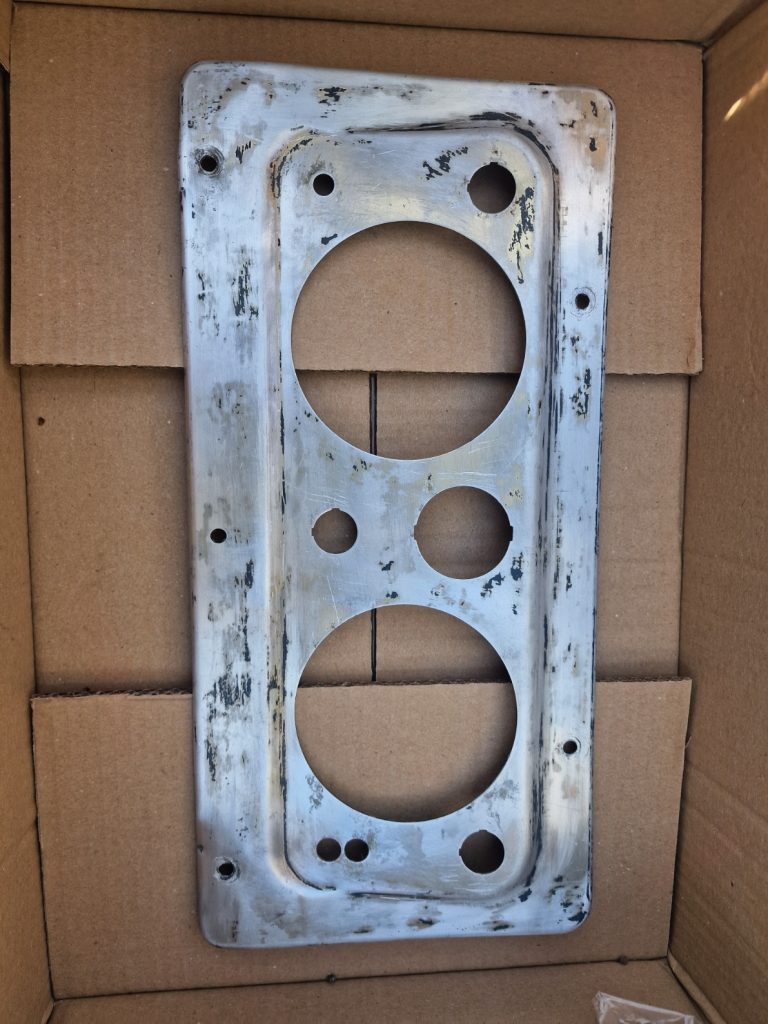
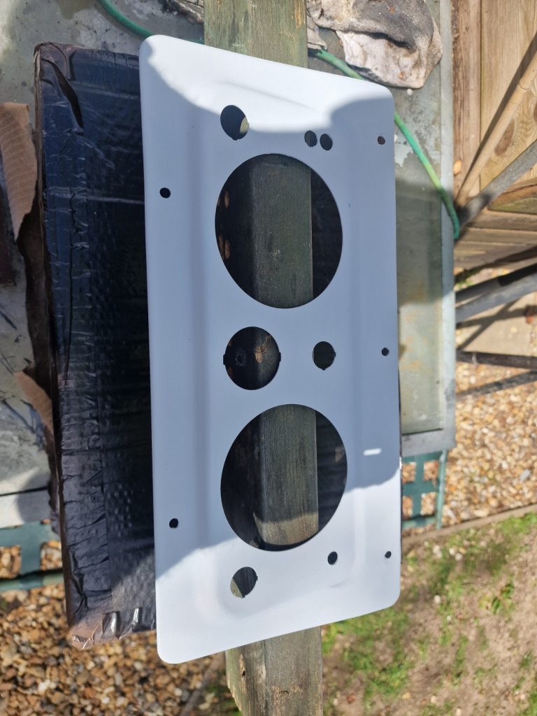
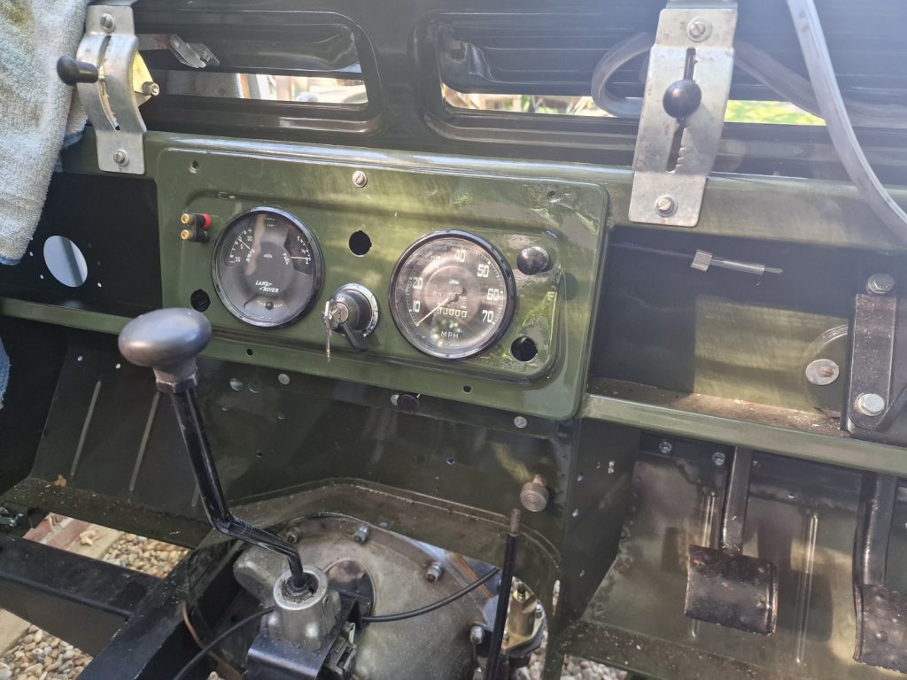
Related, I also bought a new dashboard, well second hand one, but a period correct one, so set about sorting that out and getting it painted, and populated with some stuff. Only a couple of pics of that.
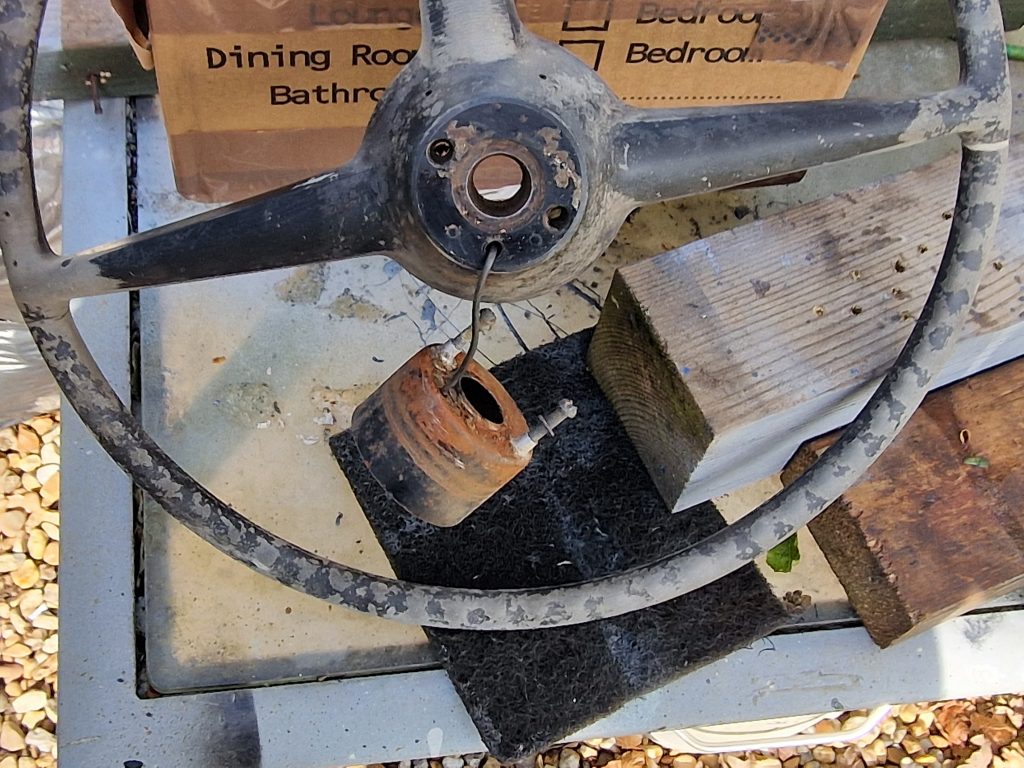
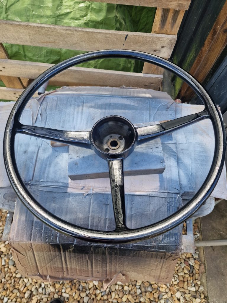
Steering Wheel
OK, so the steering wheel!! I started to clean it up and found some ominous looking cracks. I’m getting a little tired of spending money on this thing now, so set about a repair. Cut out the cracks, mixed up some JB Weld, filled them, rubbed them down and then painted the whole thing. I used a gloss black plastic paint, and then did a couple coats of lacquer. Also there is not much shiny stuff on a Land Rover, only yer headlight surrounds and the steering wheel center. So thought I would get them properly shinnied up! (re-chromed!). Waiting for them to come back
Well, thats it. Long one I suppose, but lots and lots of little bits going on. One final thing, I am pretty ready to attempt a start of the engine, so seeing if I can get some of my nephews valuable time to give me some moral support, and s shed load of knowledge, but while prepping for that have noticed a rather disappointing thing and I am really reluctant to say it, but will as it will likely mean Engine Out again at some point. the rear crank shaft oil seal seems to be leaking… and that is a B’std to re-do, it took me 3 attempts while building the engine, and clearly still have not got it right. So I might have another go myself, or, if I can get the Landy mobile get someone who knows what they are doing to re-do it, might end up being cheaper in the long run. Anyway, thats one for the future.
Leave a Reply