Main Gearbox Strip Down
After stripping and re-building the Transfer Box and Front Output Housing with all the bits and bobs in those, I started to strip down the main part of the gearbox. I have to say with some trepidation, as I have never done this before, and whenever I mentioned to people I was going to do it myself, there were always plenty of, “are you sure, its not easy, gearboxes are very complicated”.
Well as it turns out, its not that difficult after all, well the strip down anyway, the re-build might be a bit more challenging as there are a few tolerances to be aware of and make sure are set correctly.
the real purpose of stripping it down, similarly to the Transfer and Front Output housing was simply to check it all out, replace any parts that had obviously worn out, change seals, gaskets etc. so nothing major.
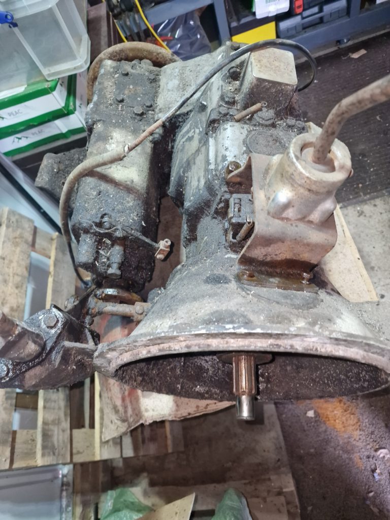
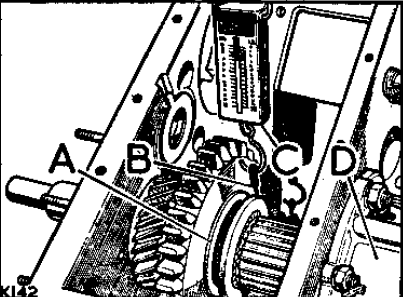
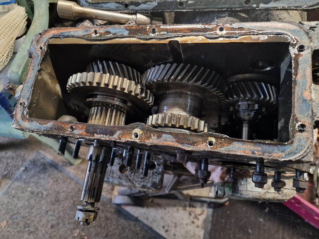
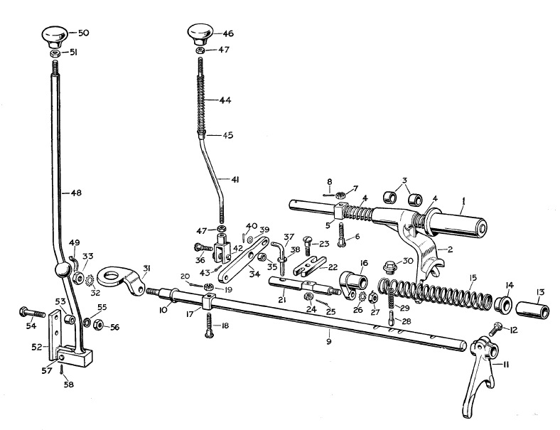
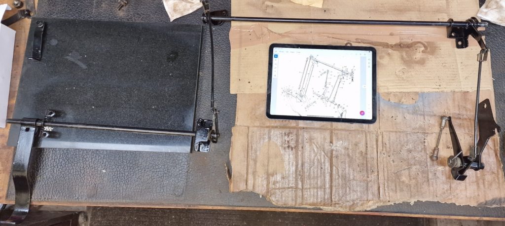
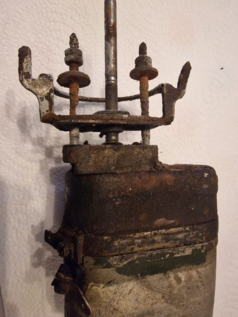
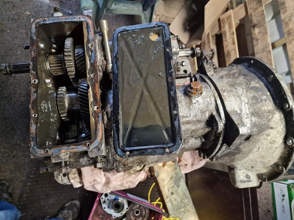
This is the part I’m interested in, the other parts are the transfer box and front output housing.
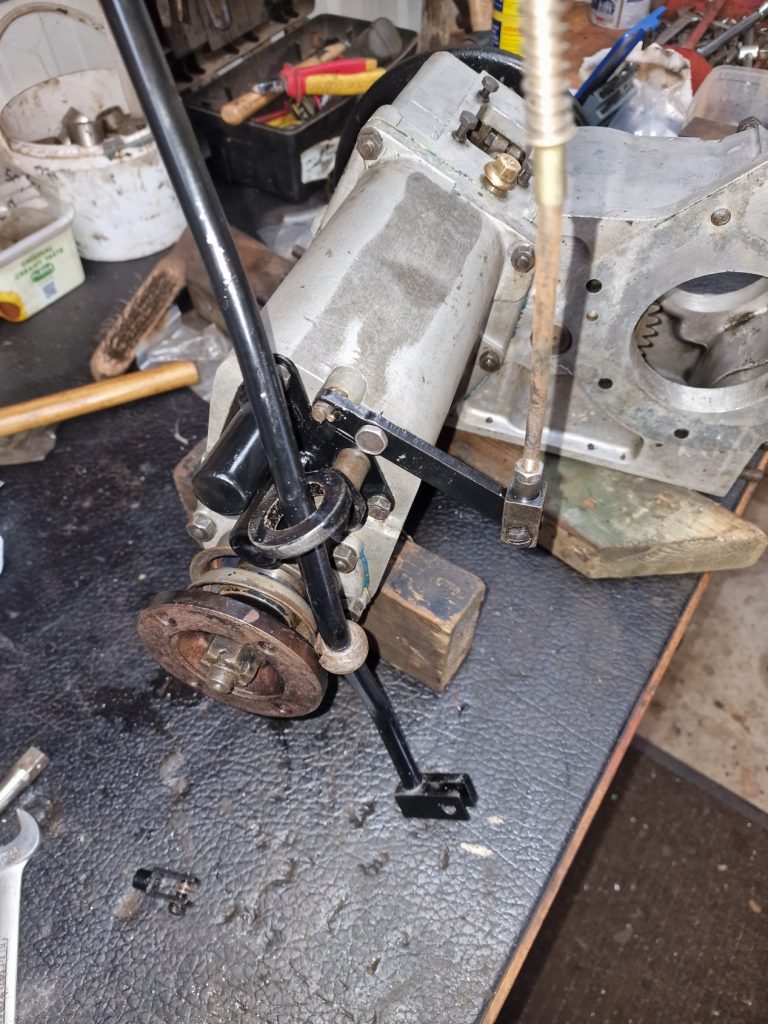
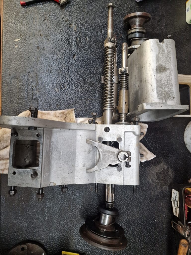
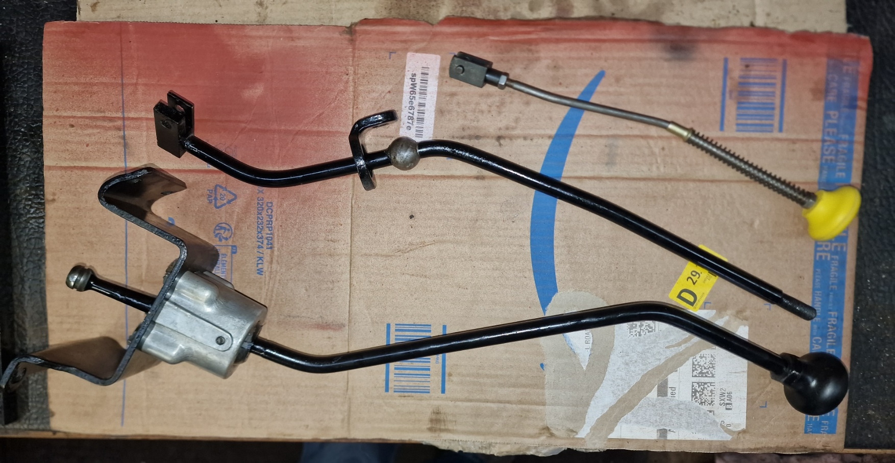
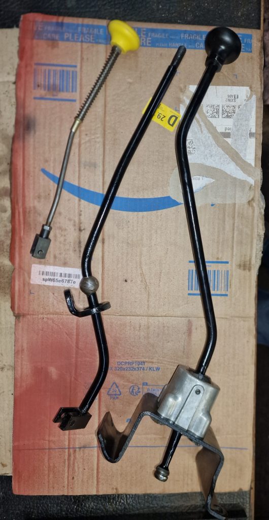
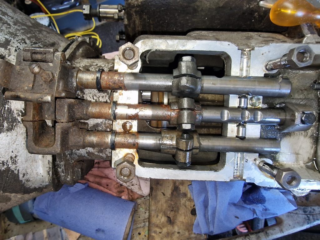
First thing (actually I had already done this, before I did the Transfer and Output housing) is to remove the Selector rods. From top to bottom, we have the Reverse Selector, 1st and 2nd gear selector and finally the 3rd and 4th selector rods.
They are a bit awkward to get out, but a bit of jiggling and out they come.

I didn’t take many pictures of the actual strip down, sorry for that.
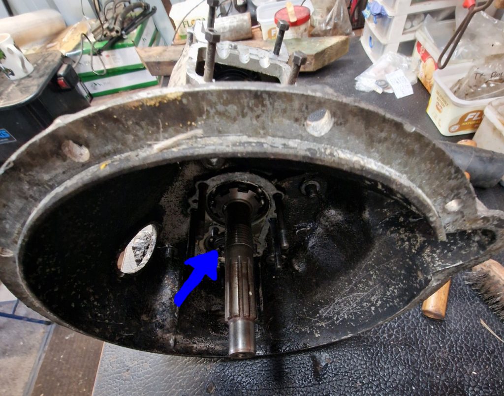
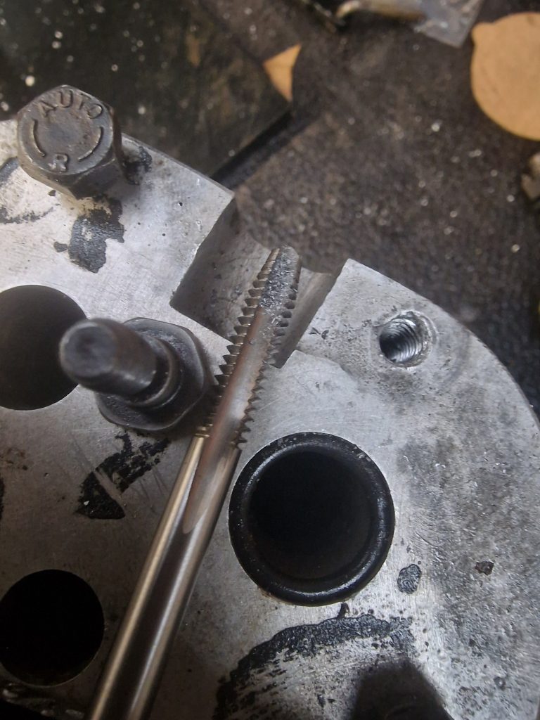
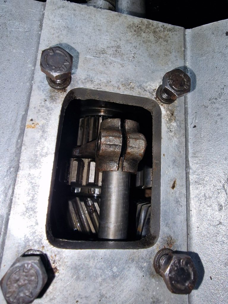
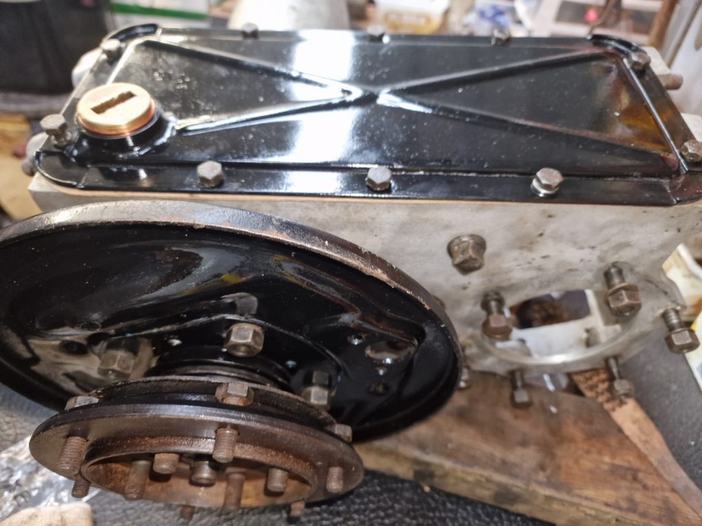
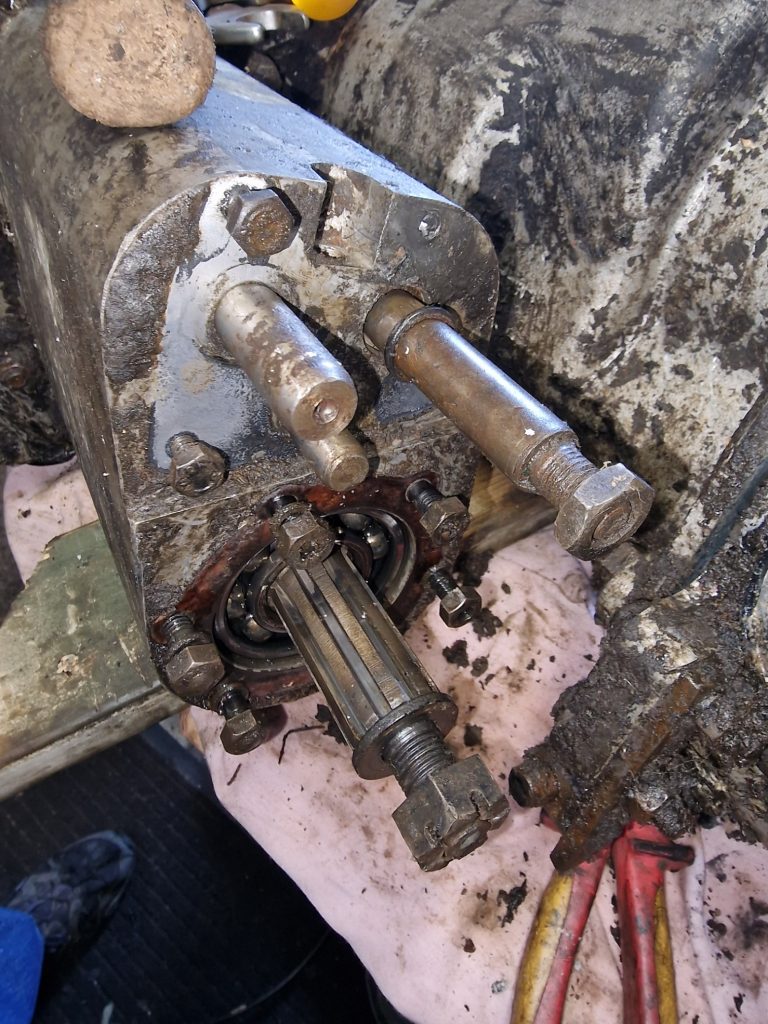
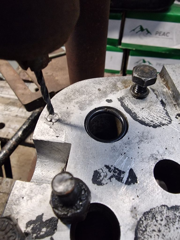
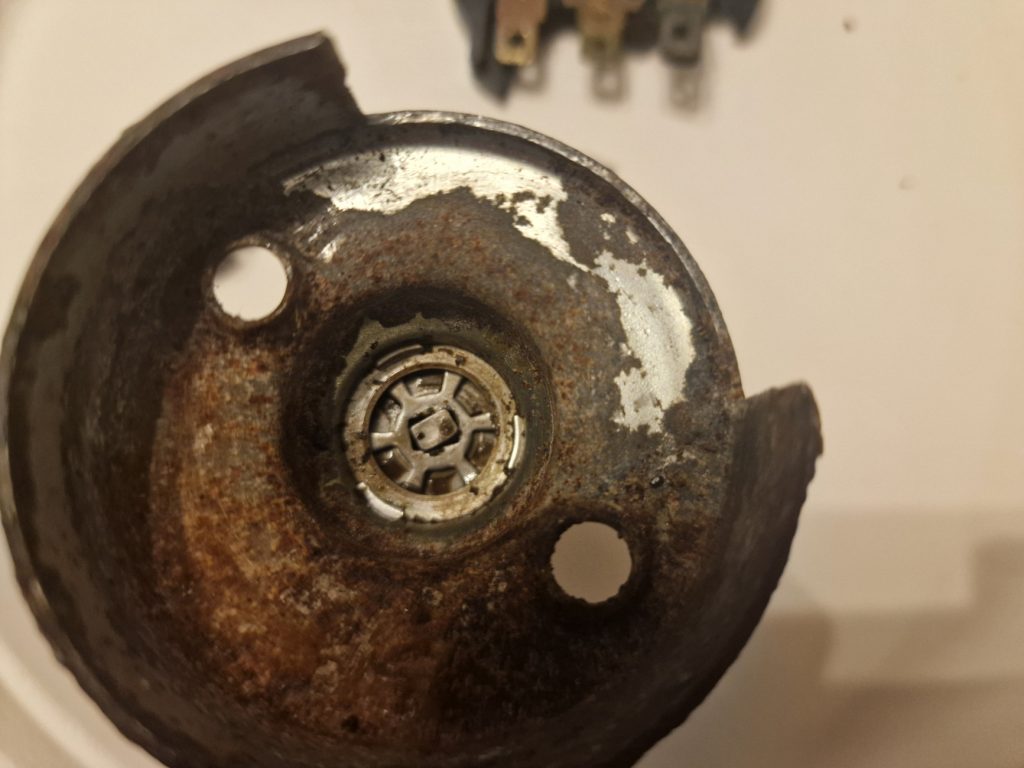
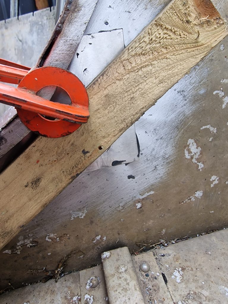
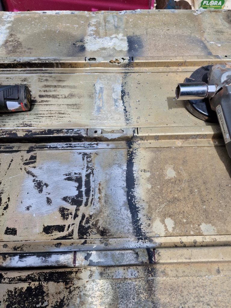
Other than a couple of plates on the back of the box, this is the first bit to come off, its a castle nut, that should tightened to about 85ft lb. Trouble is, I couldn’t find a socket to fit (no idea what size it is), so resorted to a screwdriver through the case hole (on the left) and knocked it loose with tool No# 1. (Hammer)
This releases the Bell housing from the main gearbox case, but also allows the Layshaft to come out, and some of the gears off the main shaft, leaving behind the main shaft and the reverse gear.
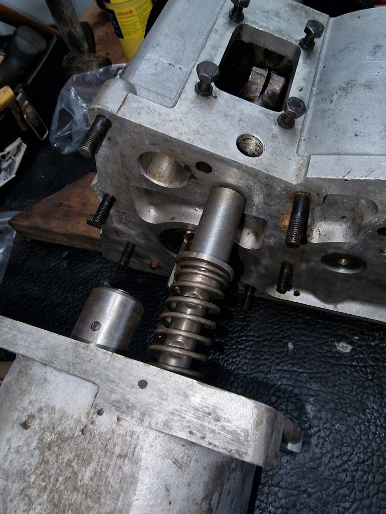
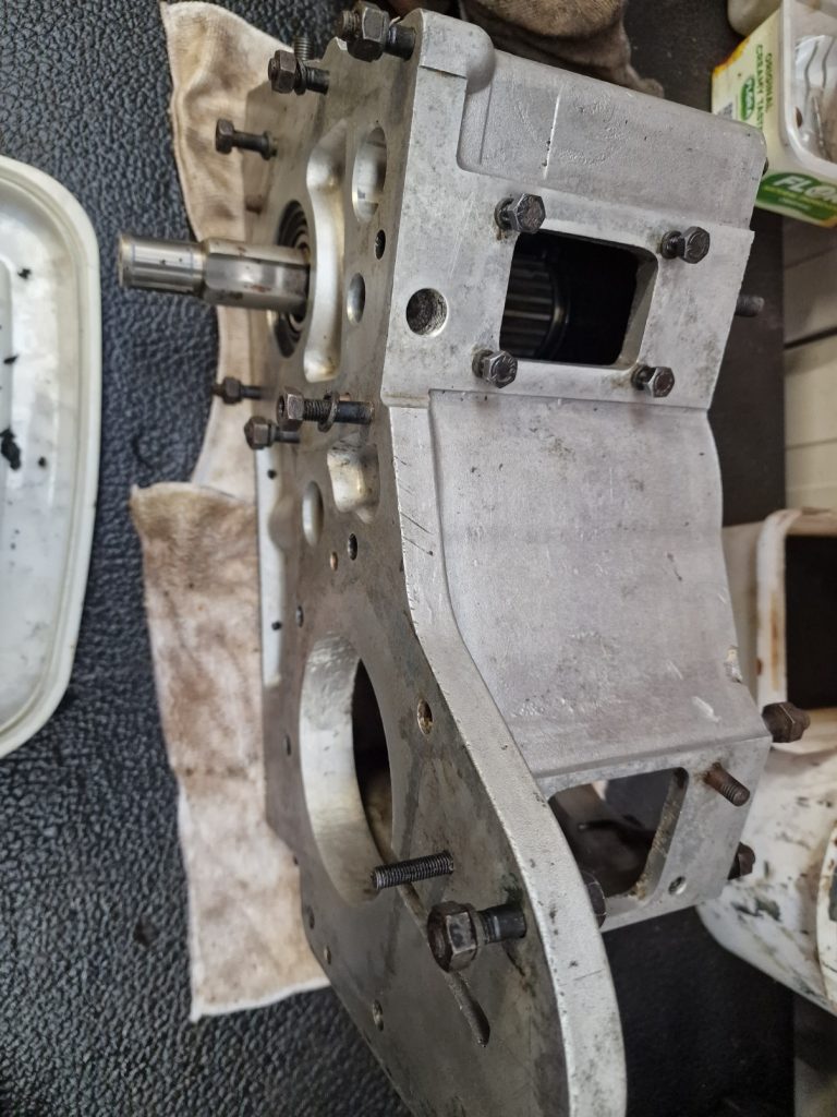
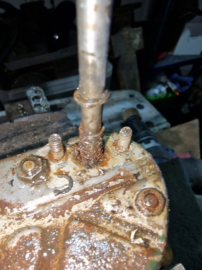
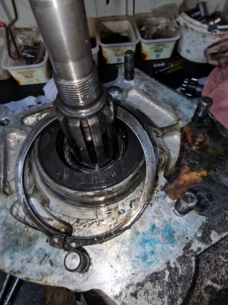
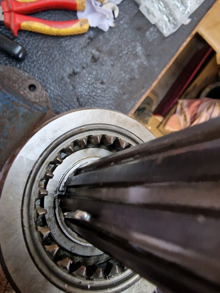
This is the top of the main shaft, which needs to be knocked out, with, I have to say took some force, but it did come out.
There is also a rather large circlip holding the bearing housing in-place, which caused me no end of frustration… I’ve only got relatively small circlip plyers, and this was a bit of a struggle.
Also took out the seal, and the bearing sat underneath it.
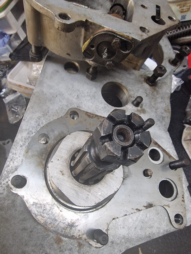
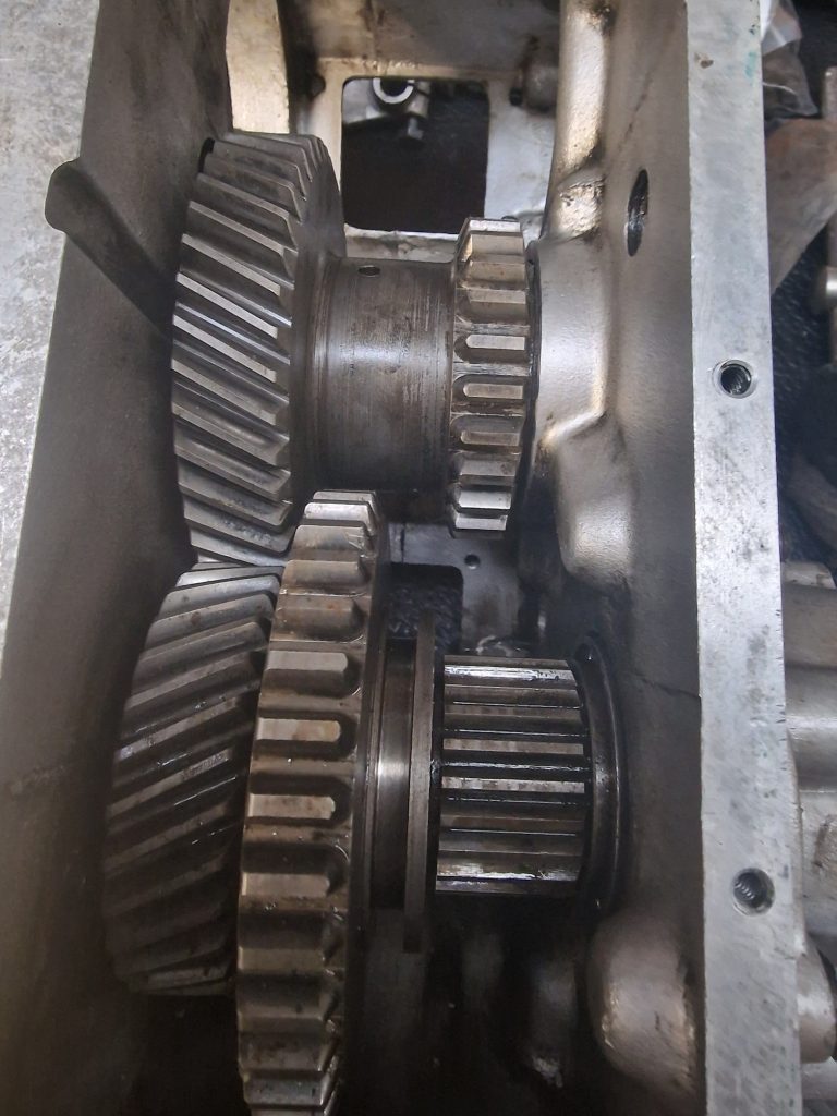
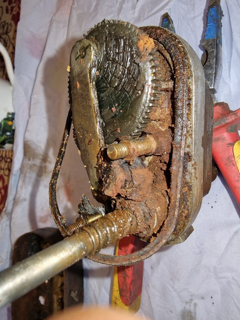
The next challenge was taking off the 2nd and 3rd gear off the main shaft.
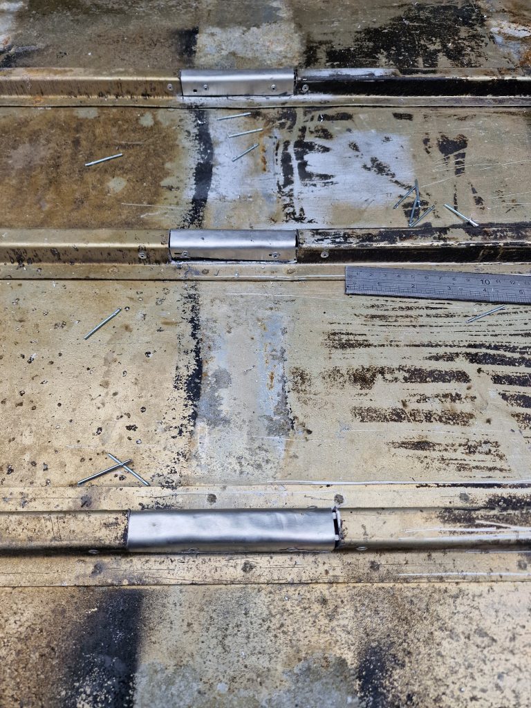
You can just about see a split washer holding the gear in position on the main shaft.
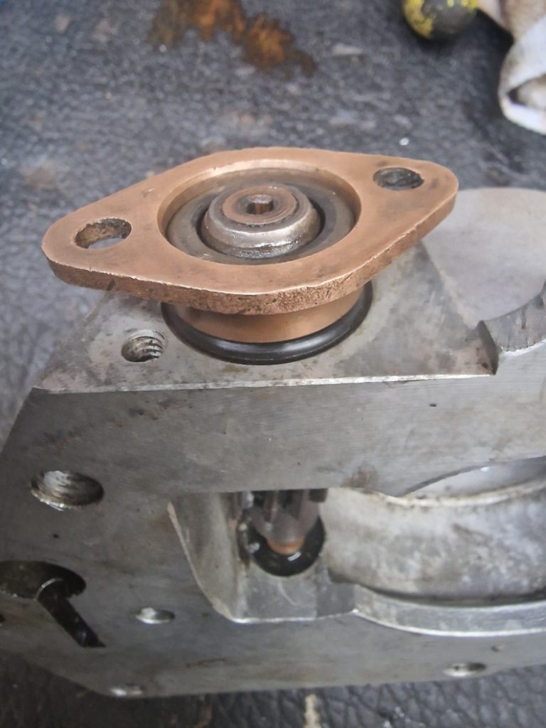
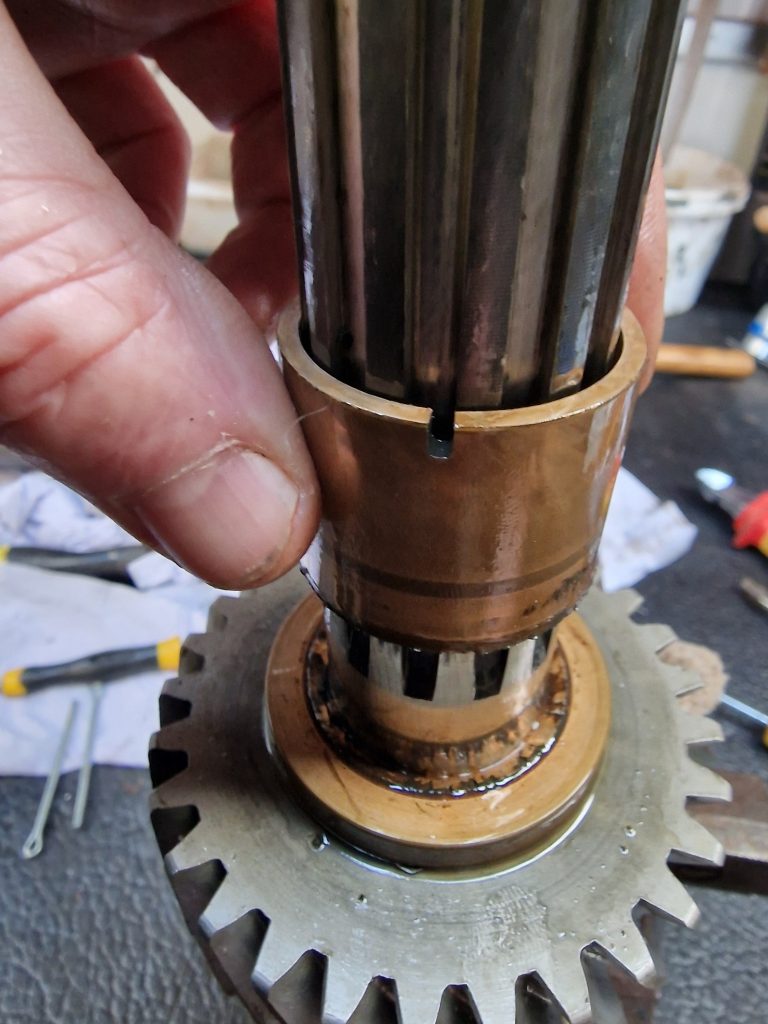
I dont have a tool to remove these, but thanks to one of the many videos online, learnt a little trick, which is to lever the washer apart, and slide in split pins to hold it. Then gently, it can be slid up the shaft, releasing the gears, and importantly a bronze bush.
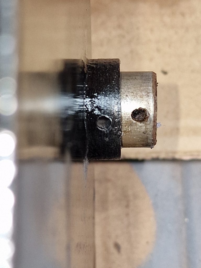
It was this bronze bush I really wanted to see, as they are apparently susceptible to breaking.
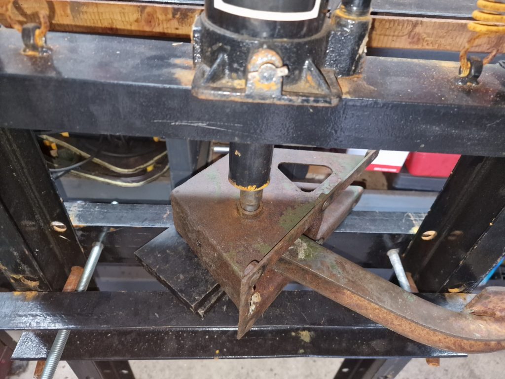
Finally, had to punch out the reverse gear and shaft, which needed the casing to be warmed up and the shaft driven out. (sorry, no pics of that at all).
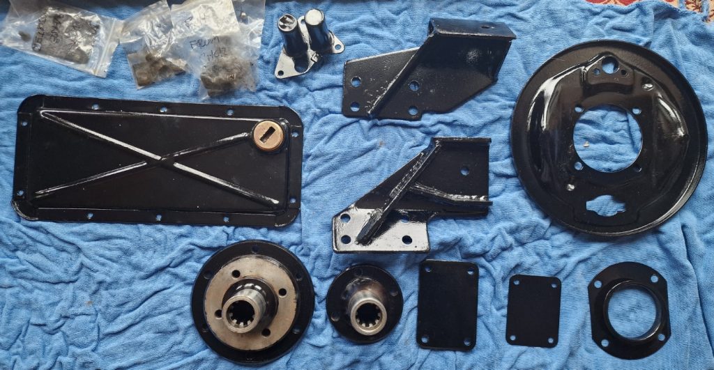
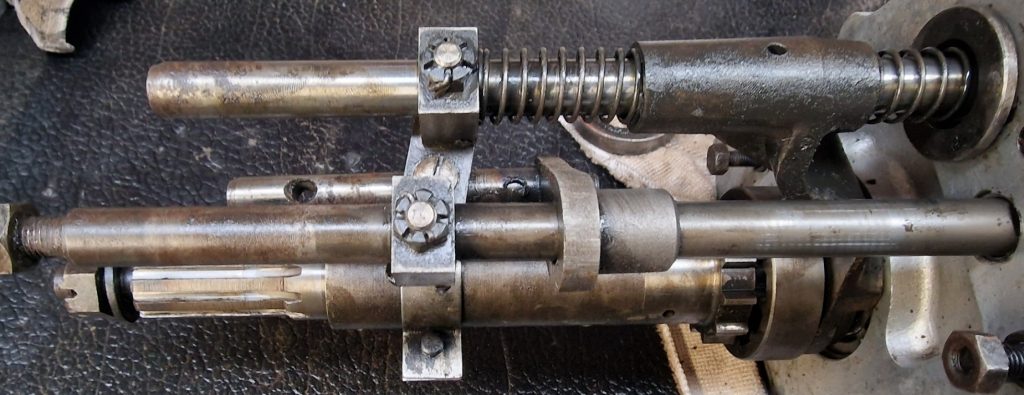
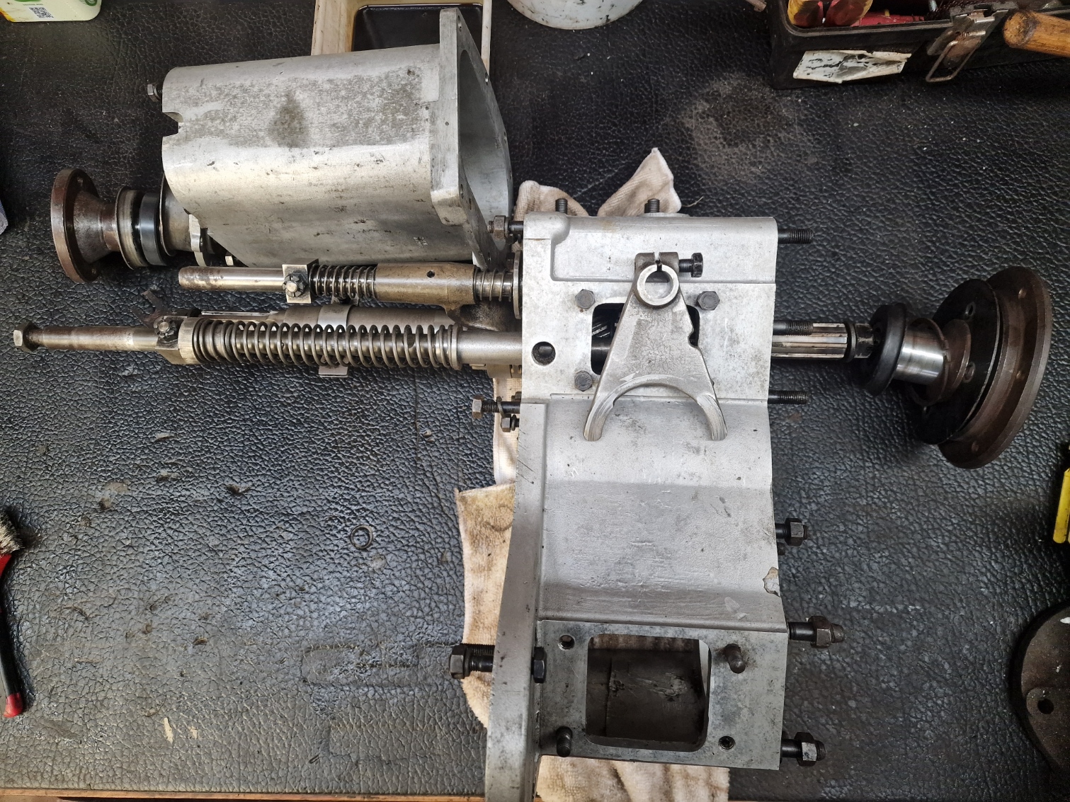
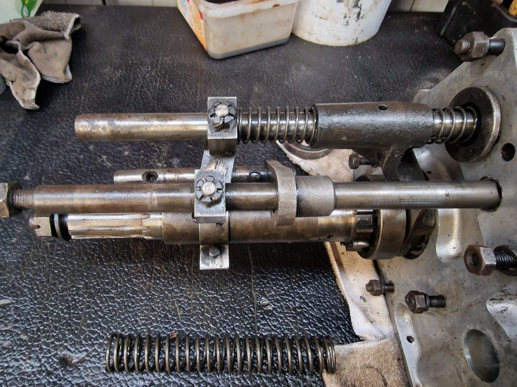
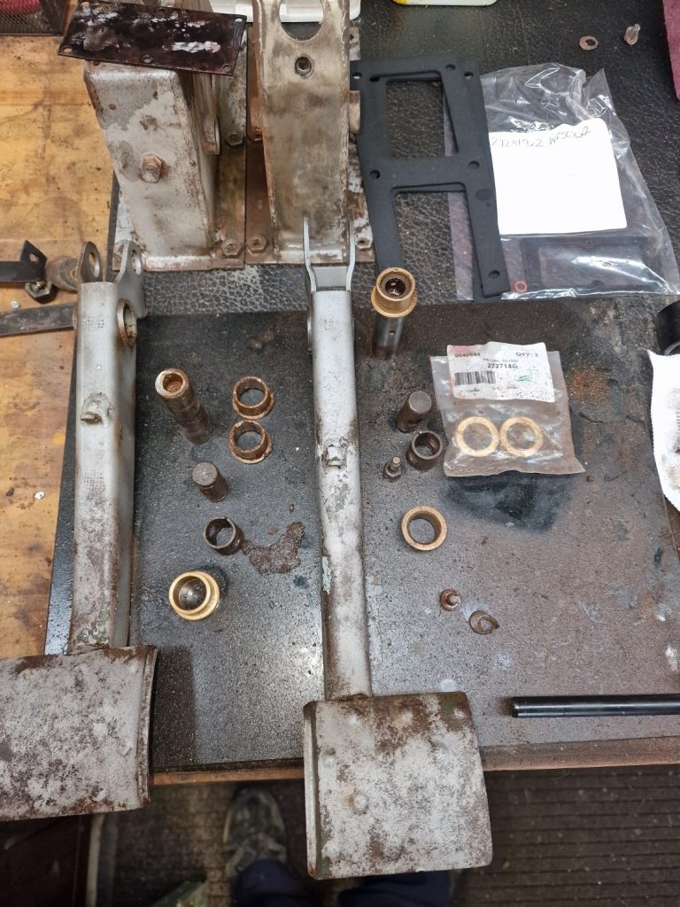
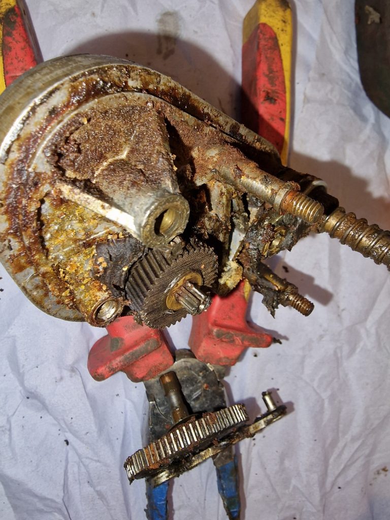
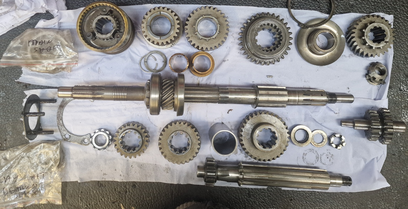
So what am I left with, well, a nice collection of gears, spacers, shims, bushes and shafts. So here goes, my attempt at an explanation of all the bits.
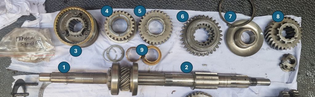
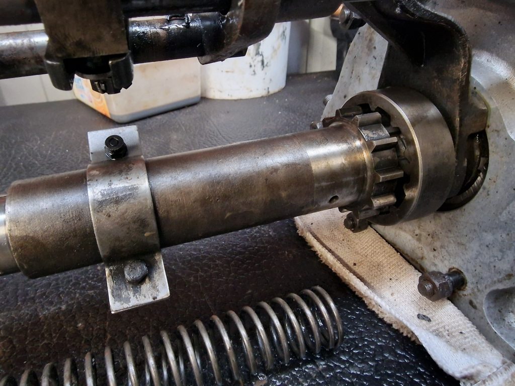
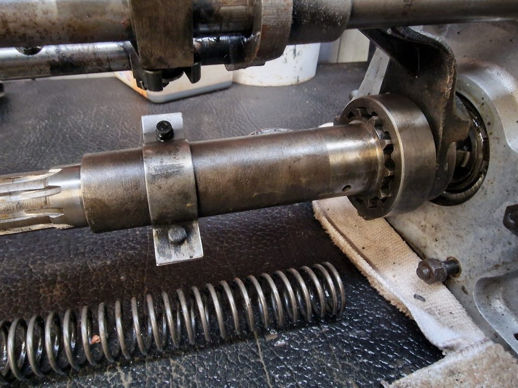
This is the main shaft, this is the shaft that holds all the driving gears, and its the moving of thsese around that selects the various gears (except reverse).
- Front half of Main shaft (Primary Pinion and constant gear)
- Rear half of main shaft
- 3rd / 4th gear synchromesh
- 3rd Gear
- 2nd Gear
- 1st Gear
- Oil Thrower
- Main shaft gear for transfer box
4th Gear, because it is selected by the Syncro, I “think” it is the gear on the primary pinion and constant gear, locking the main shaft and primary pinion together, to give drive.
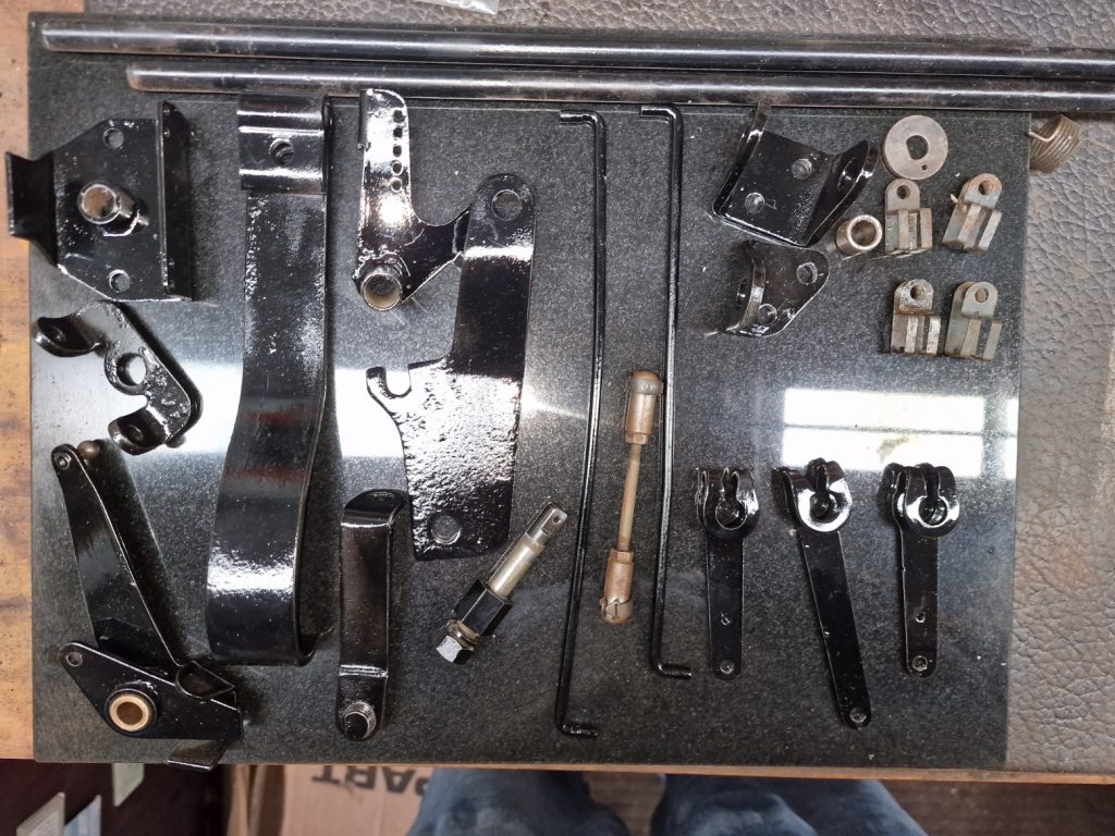
The Layshaft sits along side the main shaft.
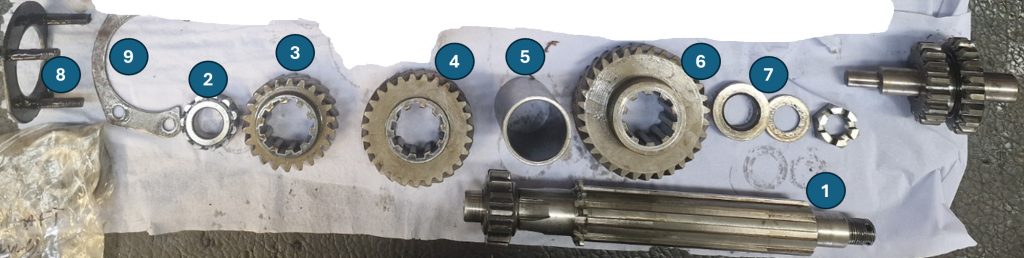
- Layshaft
- Roller bearing
- Constant gear (layshaft)
- 3rd gear (Layshaft)
- Layshaft sleeve
- 2nd gear (layshaft)
- Roller bearing
- bearing plate
- Retaining plate
The part top right, that is not numbered is the reverse gear and shaft.
Starting to wish I’d never started to write this part up.
A much better explanation can be found here. Its a video that explains things much better.
The gearbox in that video is not the same as mine, its a later version which has Synchromesh between 1st/2nd and 3rd/4th. Mine, only has Synchro on 3rd and 4th. (Old school between 1st and 2nd, double the clutch when changing)
OK, so I have it all in bits, what next. Well, the first thing I did was post some pictures on the Series2Club forum, with the question…. Are these OK or scrap? I asked because I just dont know, as I have nothing to compare with.
The answers came flooding back, and happily, the consensus was that while I could replace a few bits, generally it all looks OK, so long as I’m not planning on doing the Dakar Rally any time soon.
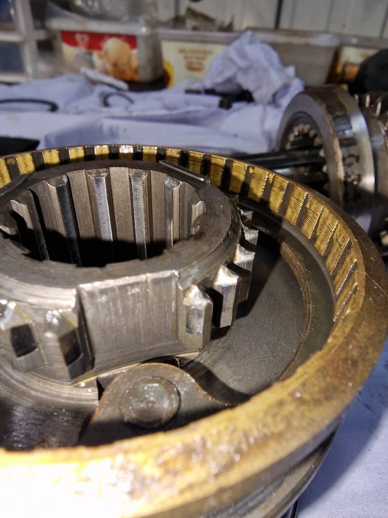
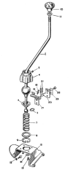
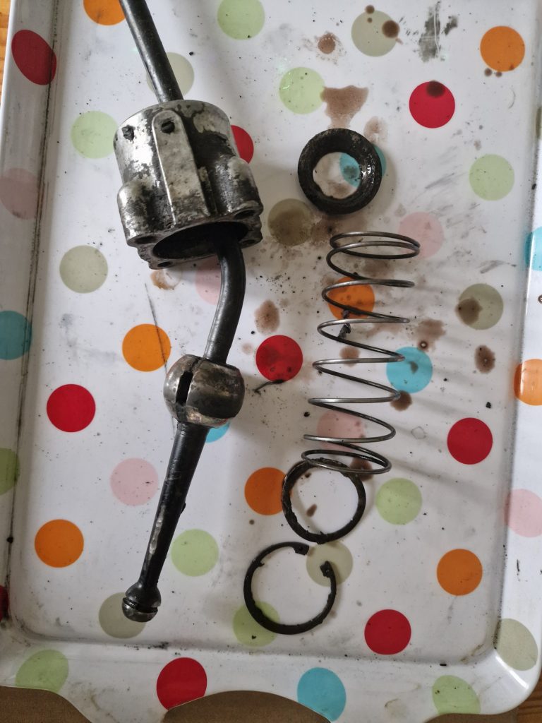
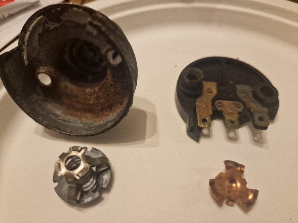
That said, there are a couple of things to look at. 1. The Syncromesh has three. well should have 3 springs that keeps the central part central as it moves between 3rd and 4th gear. One was missing, quite common apparently.
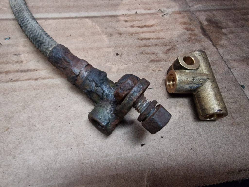
The second issue was that the Bronze bush that is a common point of failure, had actually failed so that needs replacing also.
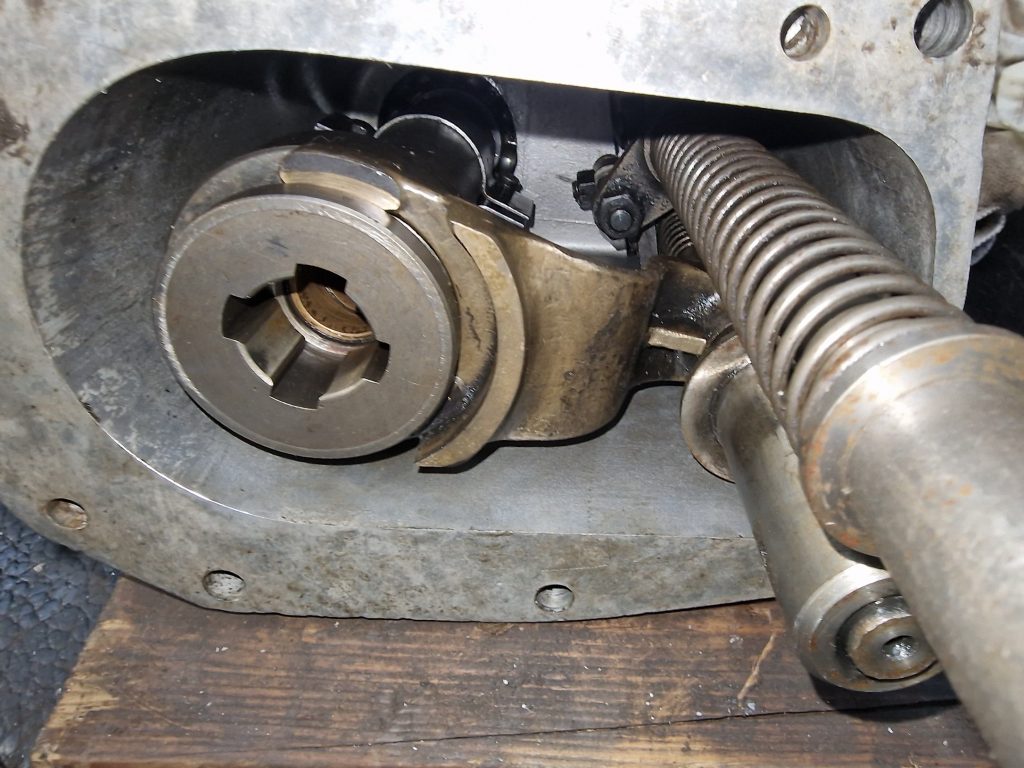
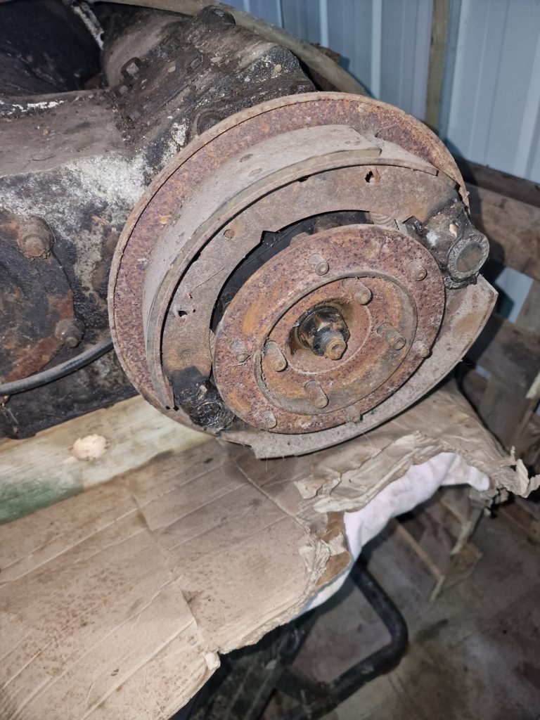
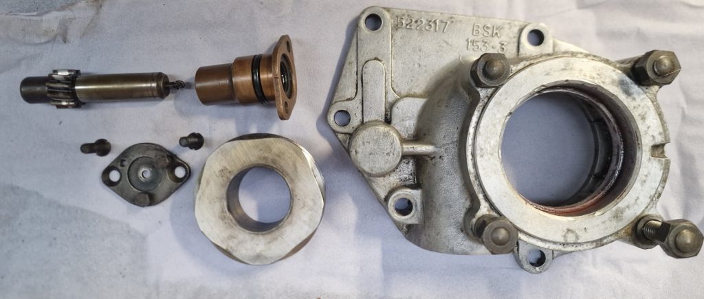
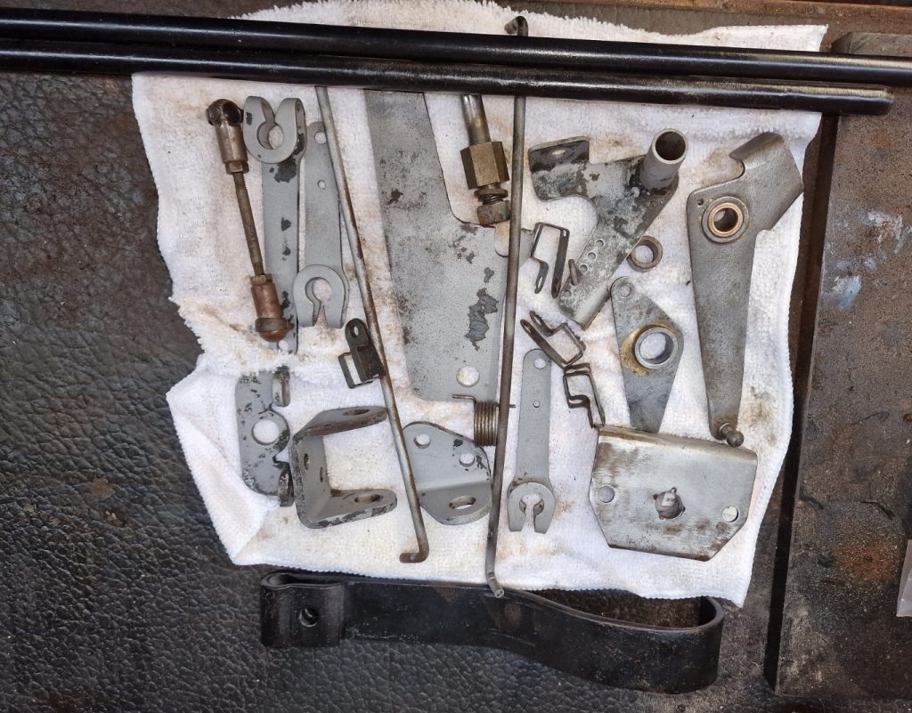
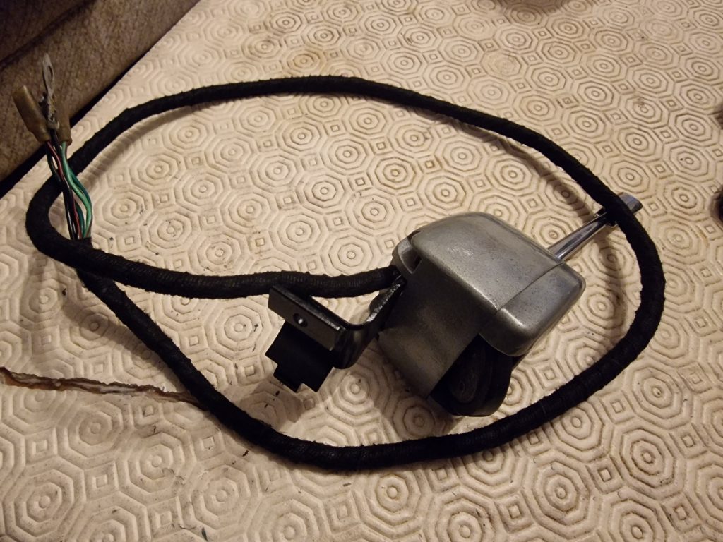
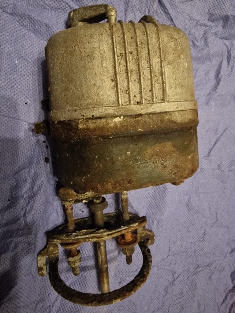
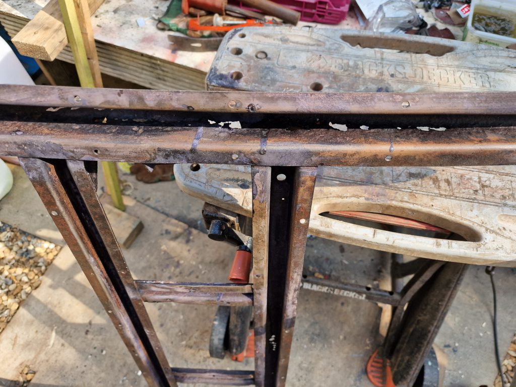
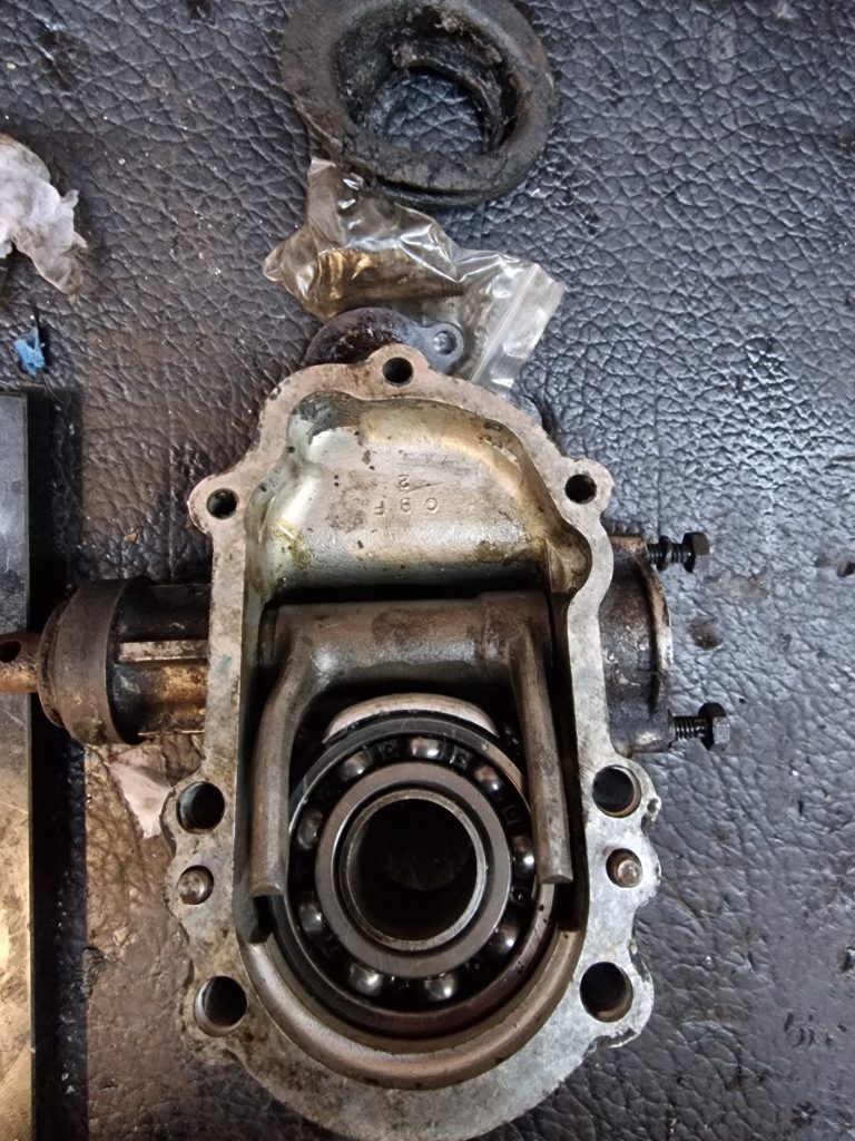
Final part, for completeness is the clutch housing and mechanism. Not taken this apart just yet, might leave as is, need to look and see if it could do with any new parts.
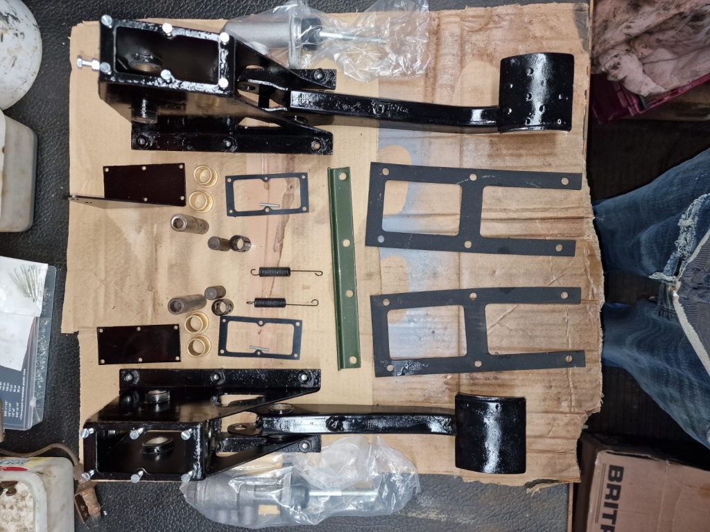
So thats the Gearbox stripped down, all I need to do now is to clean it all up, casings, gears, shafts etc. order some new parts, and put them all back together. Thats where I need to take my time, make sure all the tolerances are set accurately. Had some really good advice on this also from the Series2Club forum.
I did consider replaces one of the gears that is showing a little more wear than the others, and the bearings, but the consensus was that what I have will likely be perfectly ok, and I wont really know for sure until the gearbox is being used. So it will go back together with what I have and see how it performs when I get the drive Isobel for the first time! If its not right, we’ll it will simply have to come back out and re-built again, but this time knowing what to focus on and what actually does need replacing, if anything.
Thanks again for reading, back soon..