December 2025
Its been a while sincle my last post, back in September 2025, when I completed the engine build. Since then, I;ve beemn busy doing lots of other stuff in and around the house, my wife, brother and sister in-law took a short break in the New Forest, and more recently, prepared for Christmas. All the time thinking about Isobel and what I should be doing. Took a couple of weeks off over Christmas, with the plan to crack on, which I did.
This one then is a bit of a mix of topics, as I spent alot of time doing stuff I dont really need to get done, partly becuase I was short of a few parts, but also becuase I dont do cold very well, so here goes.. A bit of mix and match.
Engine and Gearbox
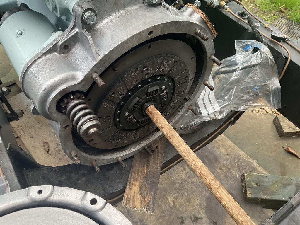
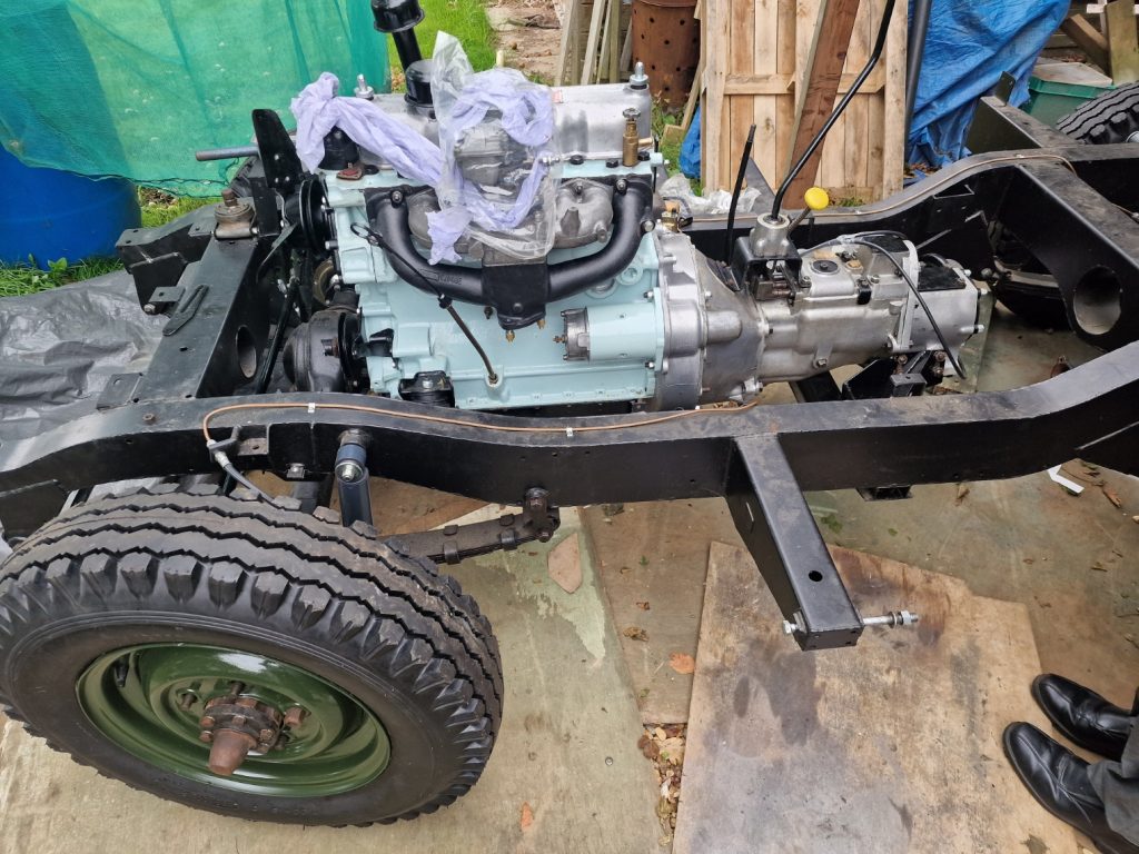
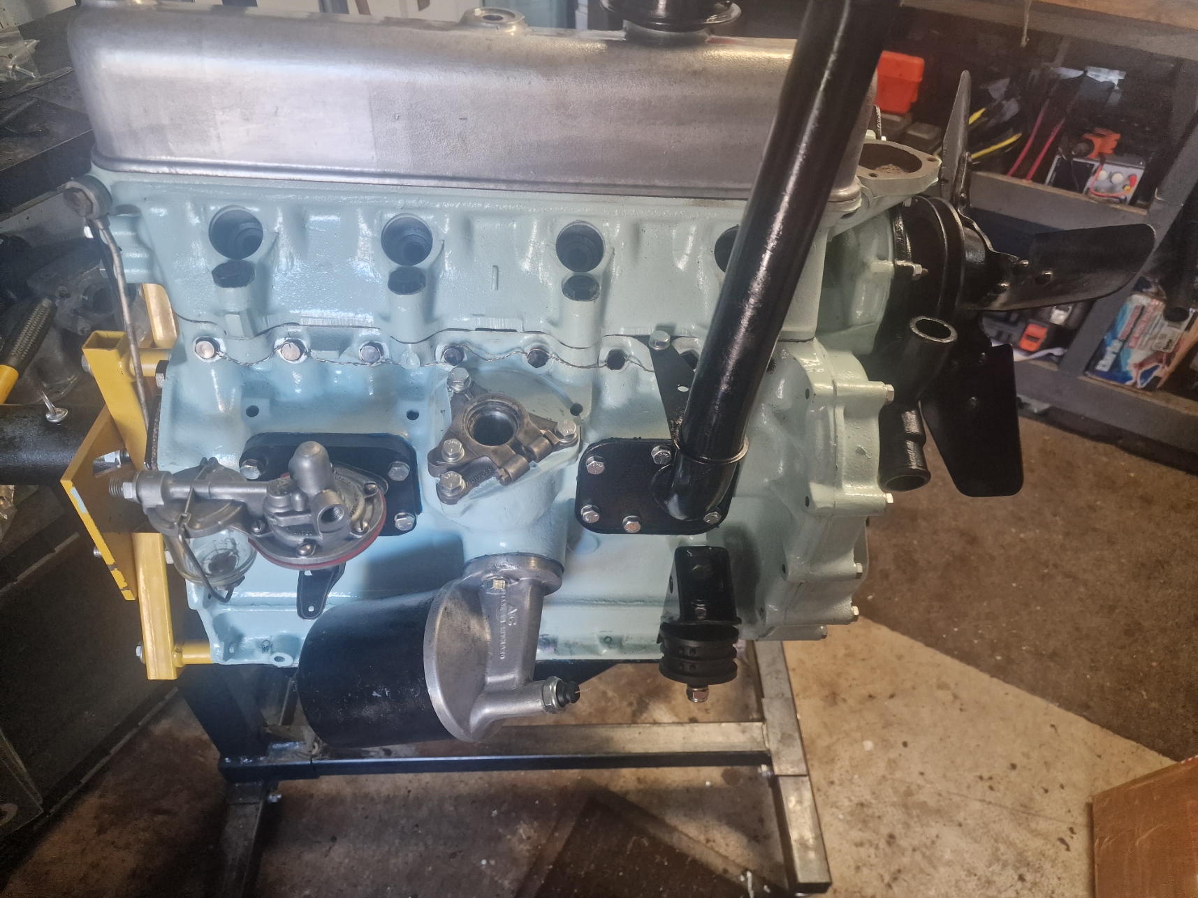
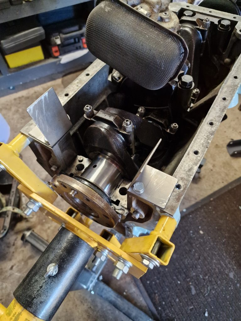
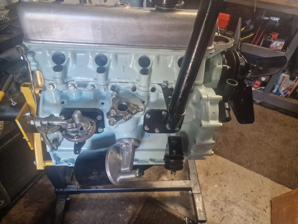
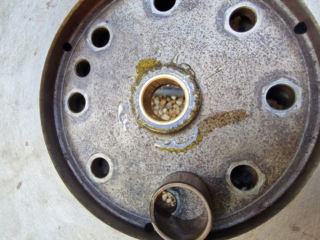
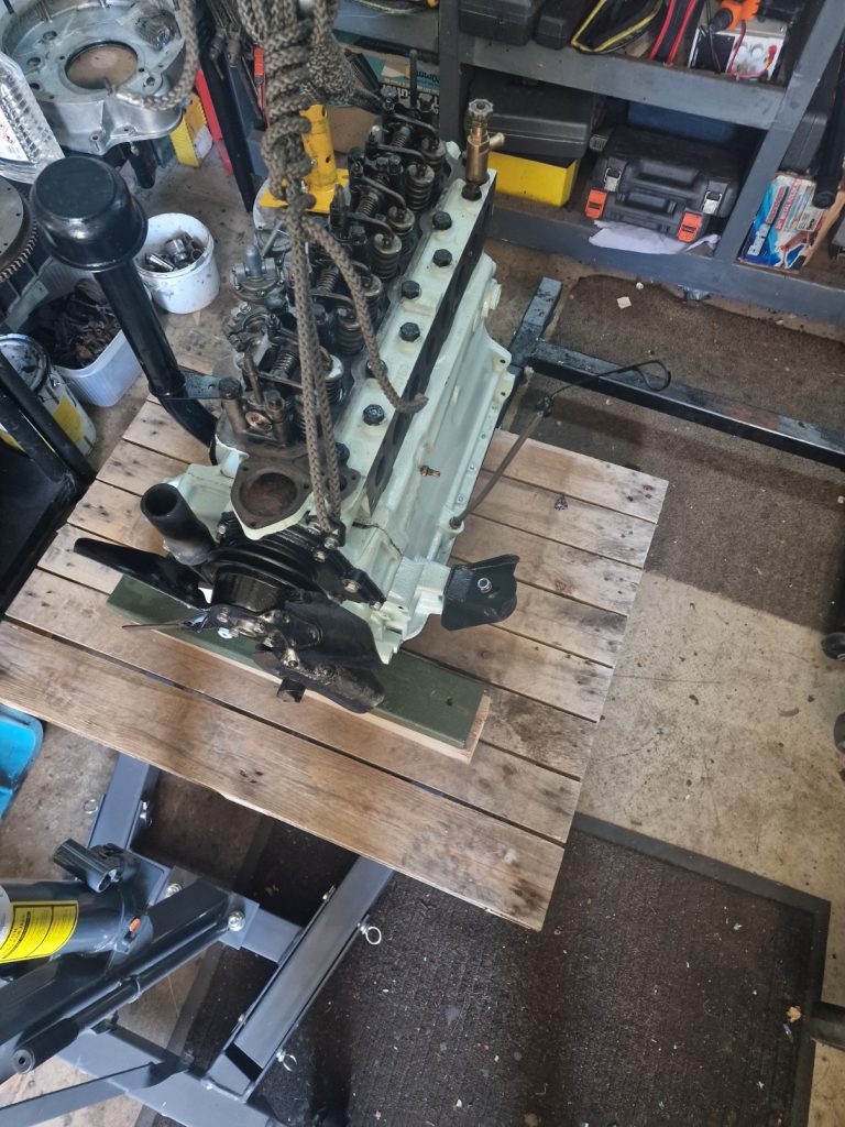
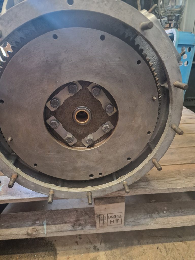
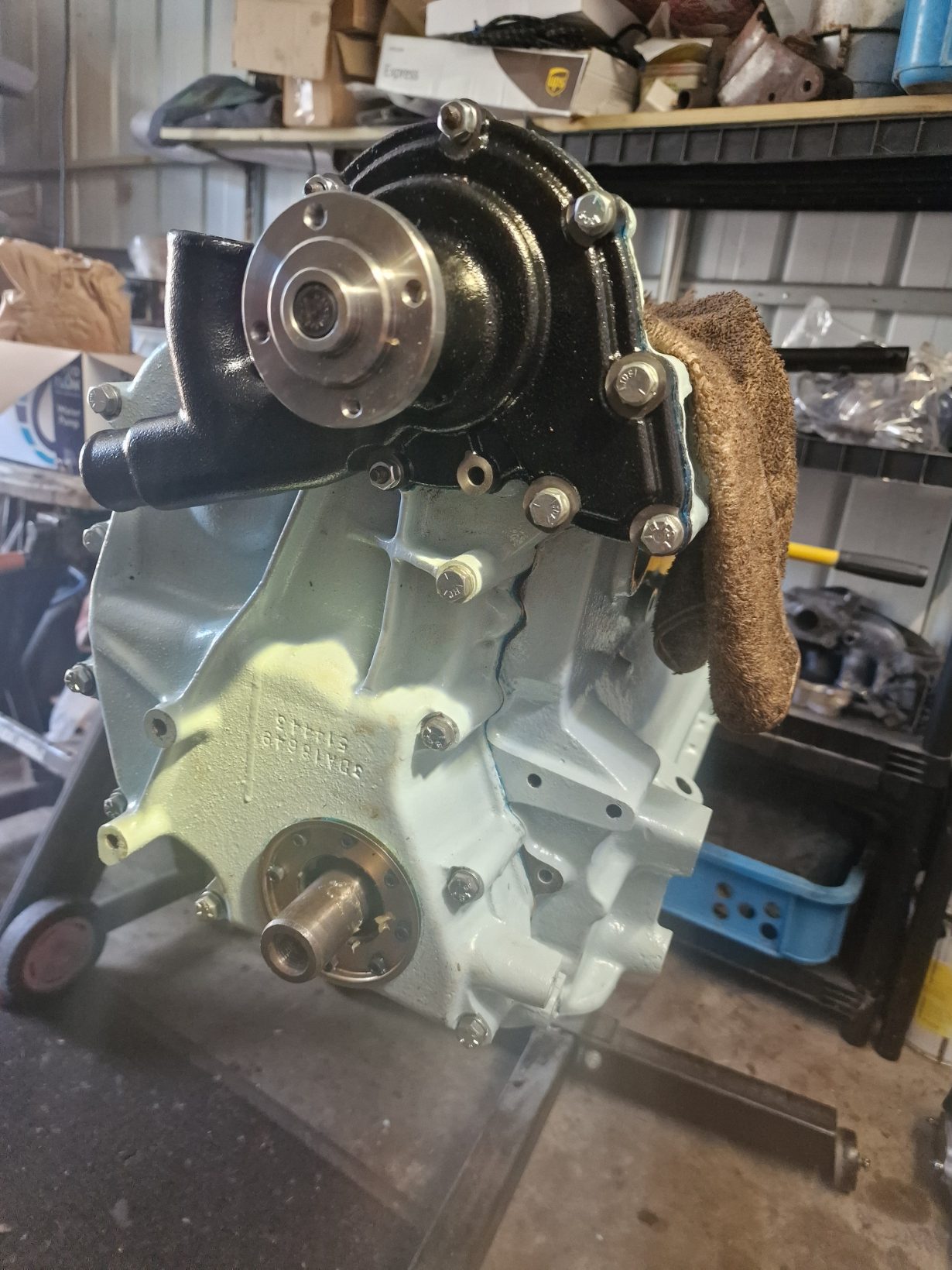
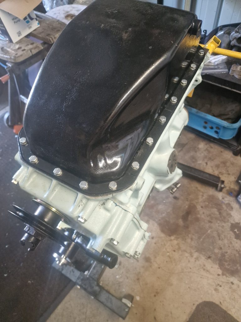
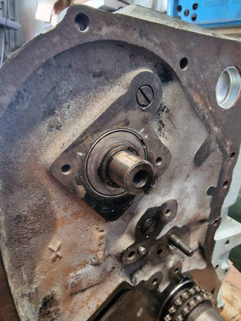
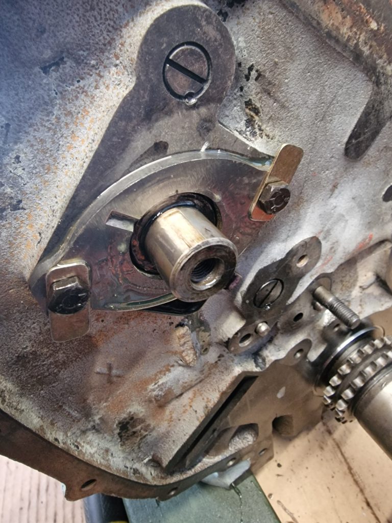
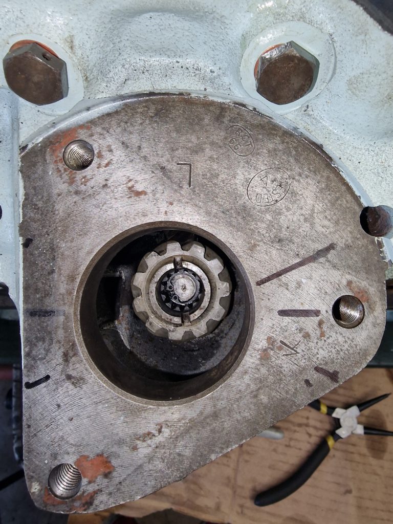
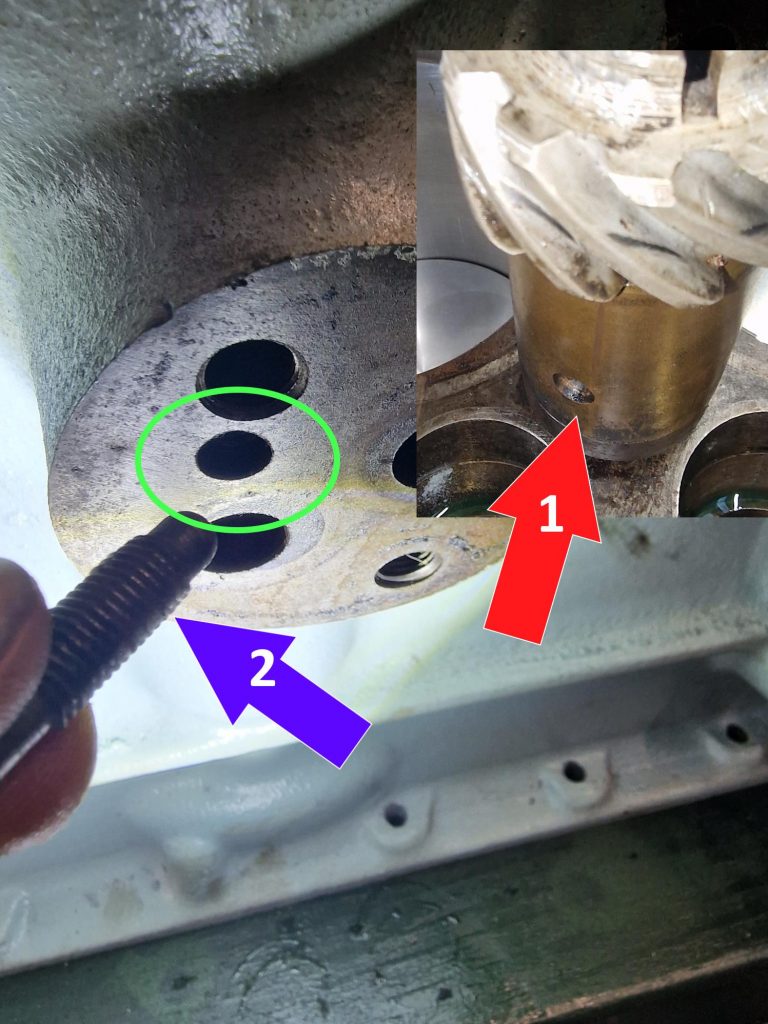
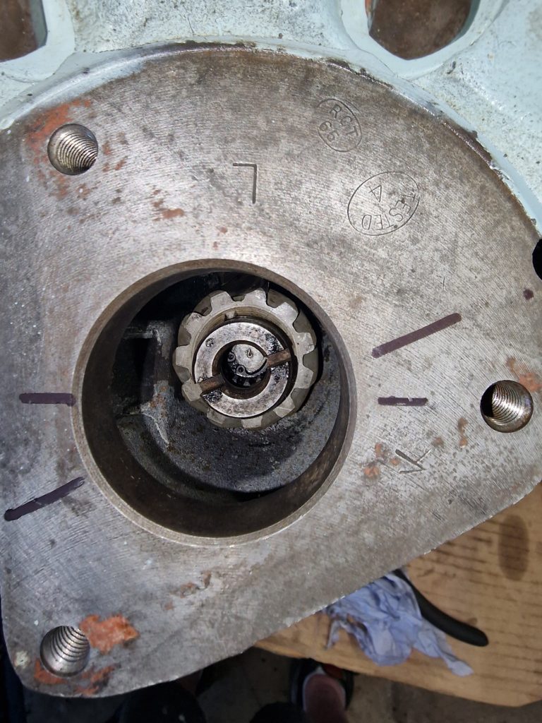
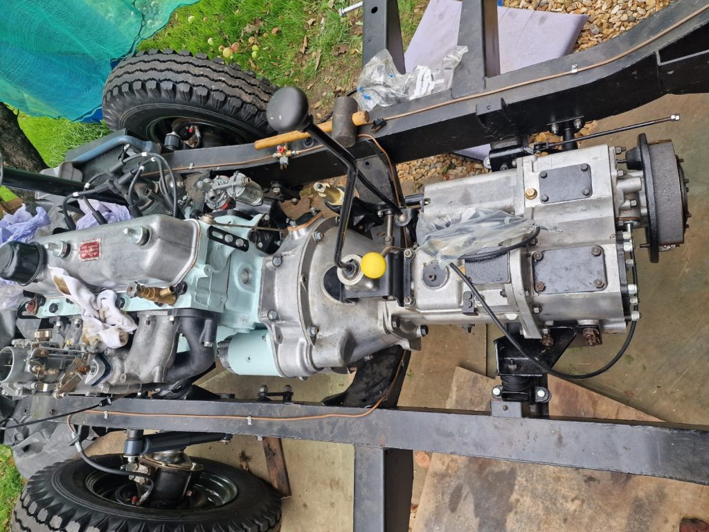
My last post was completing the engine re-build and getting it and the gearbox, along wiht a new clutch into the chassis. One thing I did forget was to grease the bush in the flywheel and also the clutch withdrawel mechanisum. So, first job was to remove the gearbox and grease those parts up.
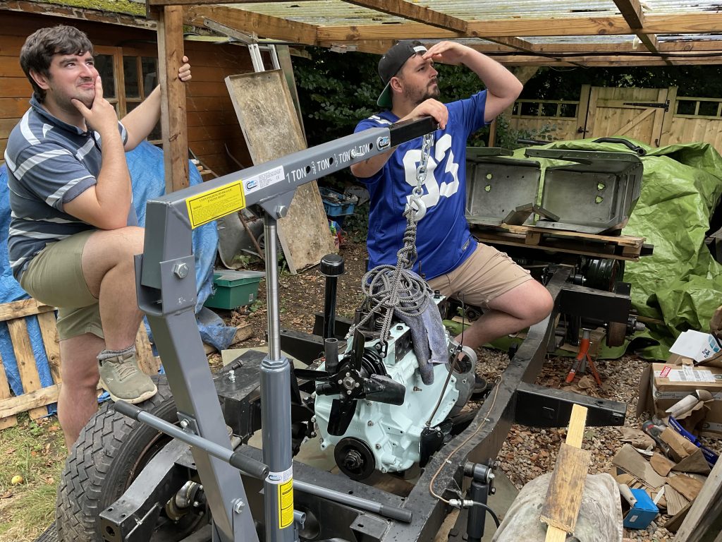
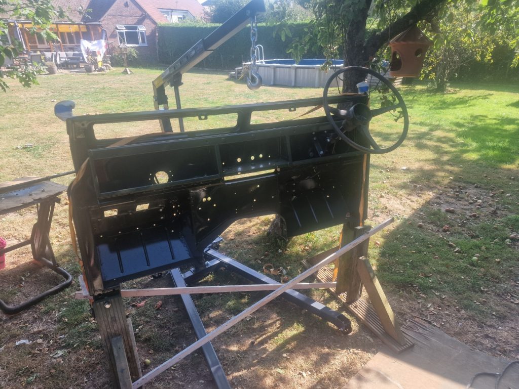
Next, was to put the bulkhead onm which I did manage to get done although with some difficulty, as I did it on my own with the engine crane. Anyway, all on and loosly bolted up.
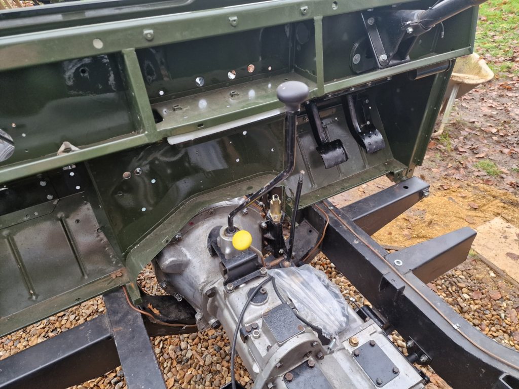
Before the bulkhead went on, and before my break, I did install the peddles along wiht the master brake and clutch cylinders. Another little error here, I had to correct, I had the wrong master cylinders on the wrong peddles, no idea why I did that, but I did. Swapped them over, so all good now.
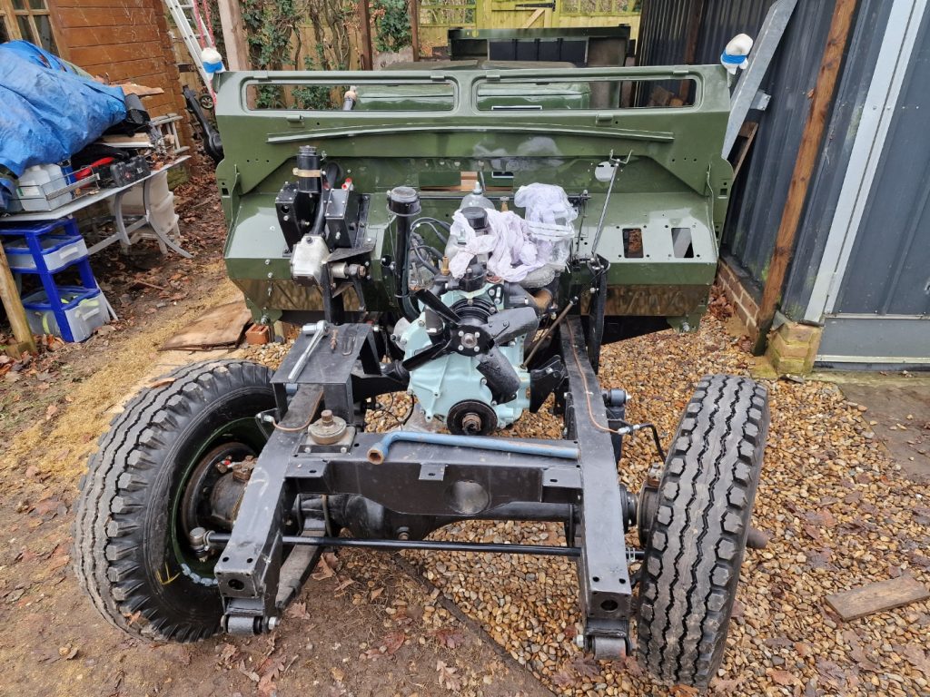
Now I have the bulhead on, I can move the land rover back in its car port a bit futther. to do this I put the tub onto the chassis, and just could no resist the tempation to all a little of the galv cappings and try the tailgate on. Only did the corner cappings.
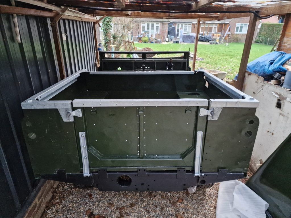
The next obvious thing would be to bolt the tub onto the chassis and line it up, but didnt have enough of the right size bolts, so parked that bit for a while. The tub needs to be put on, lined up before the bulkhead can be fully tightened, and probably want to do this before adding too much else right now, so needed something else to focus on.
Propshafts
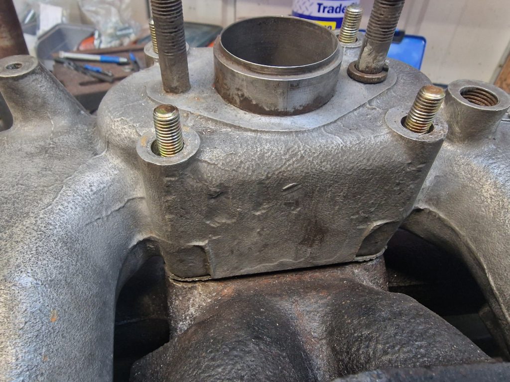
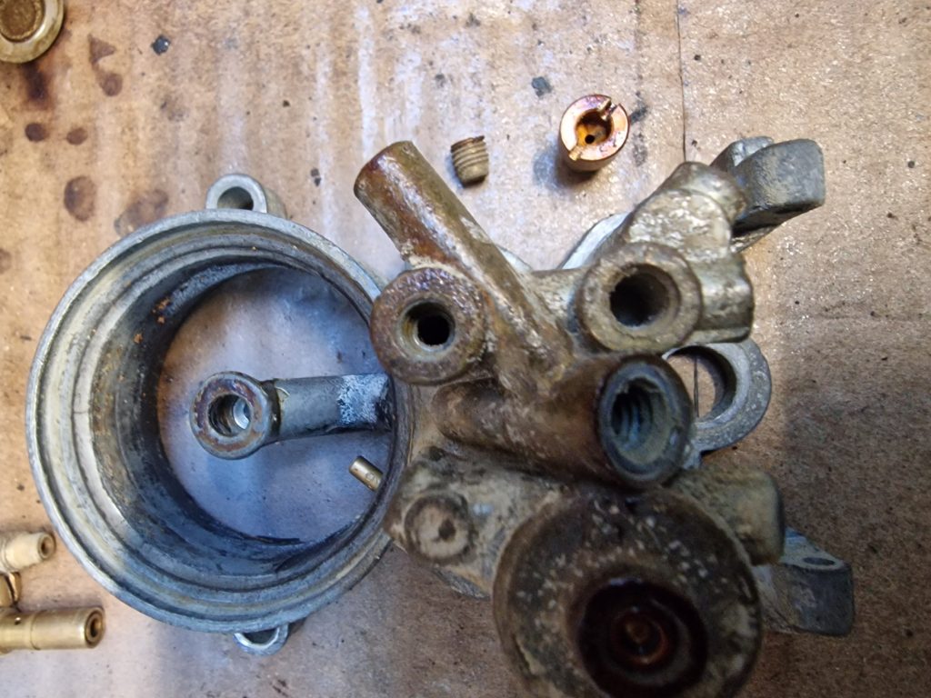
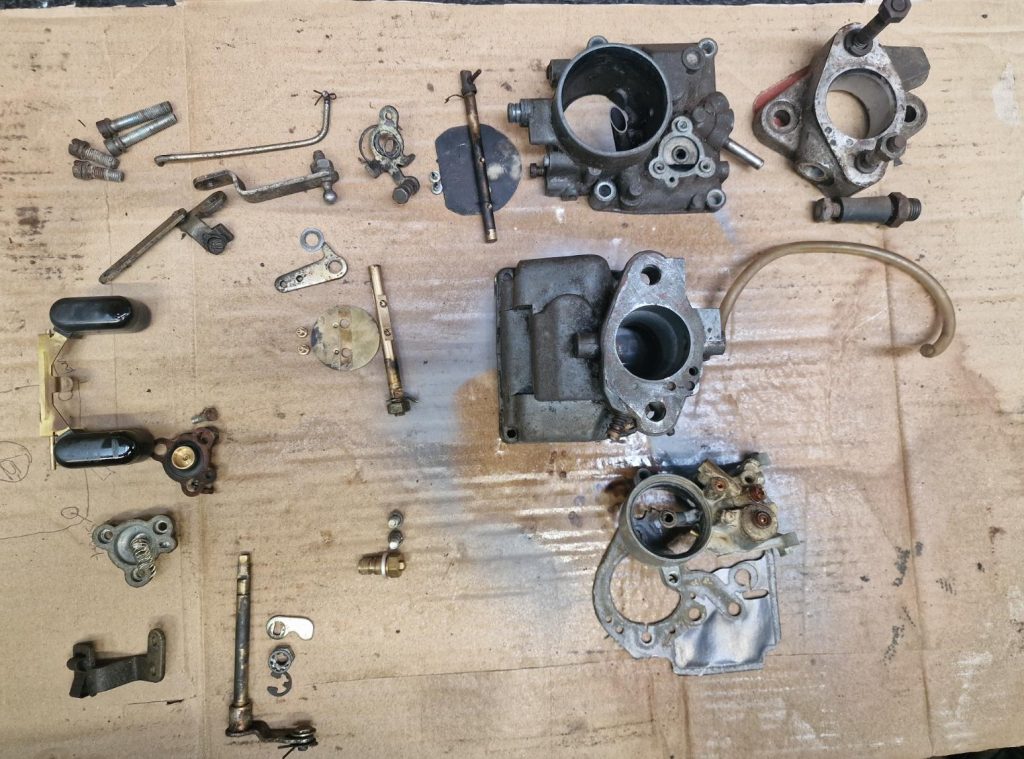
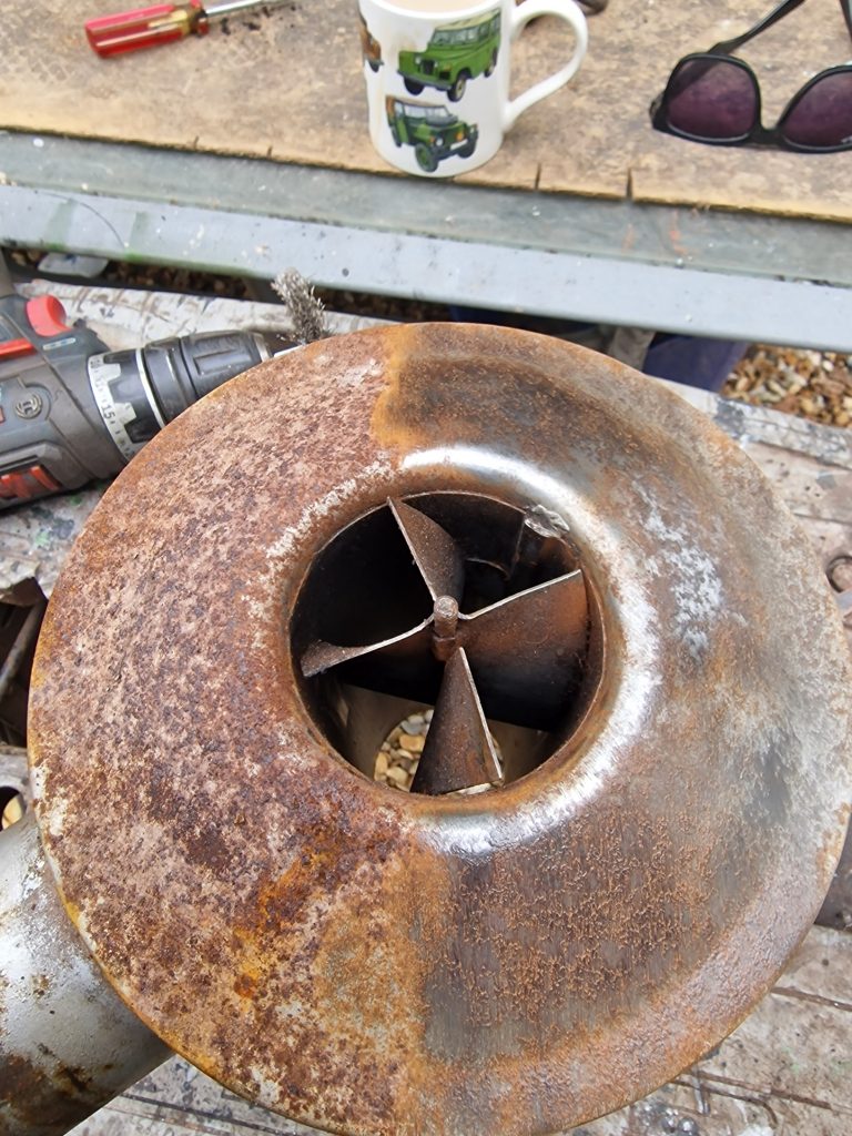
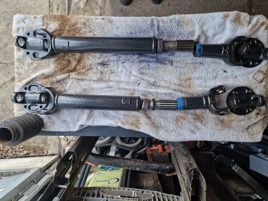
A couple of things have been tucked up in the corner of the workshop I’ve been avoiding for a while are the two propshafts. So decided to start restoring them.
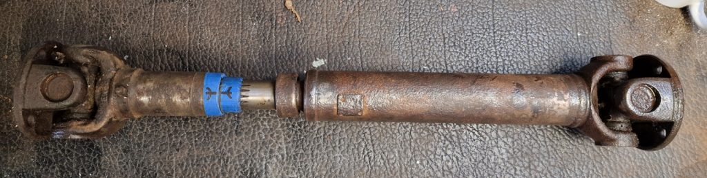
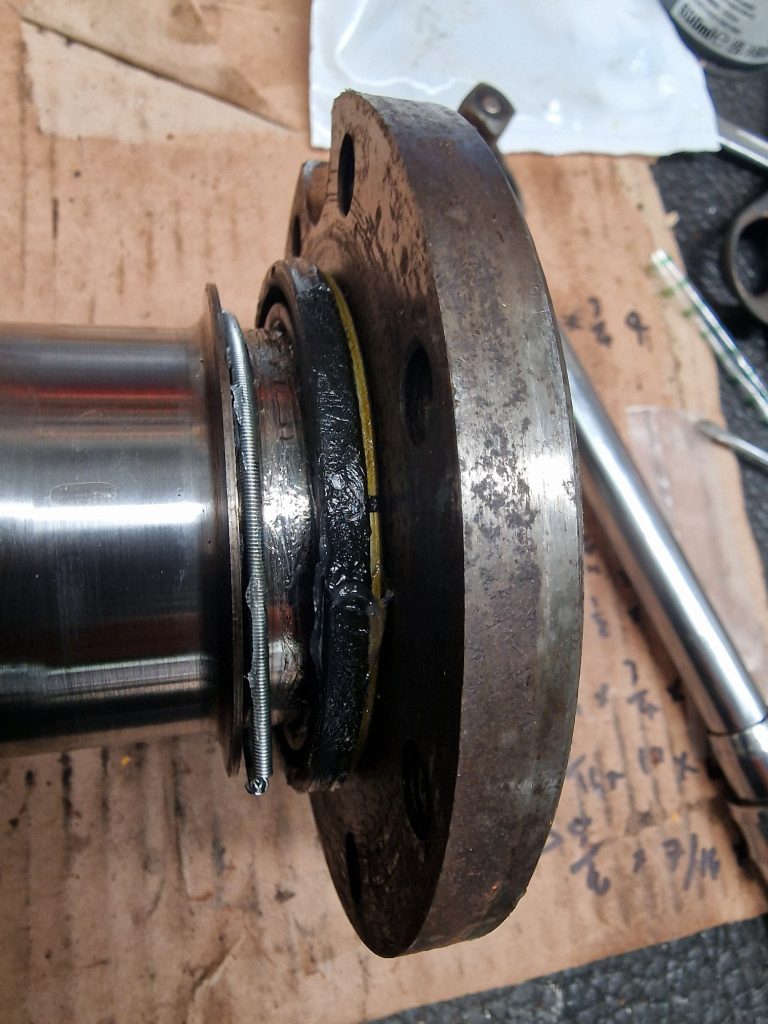
This one, has been cleaned up a bit, they were both way more crusty than this, and took a while to wire wheel them clean.
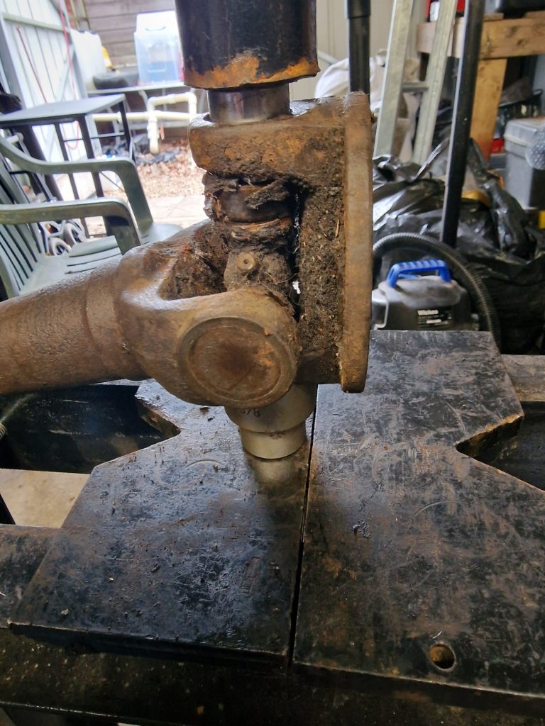
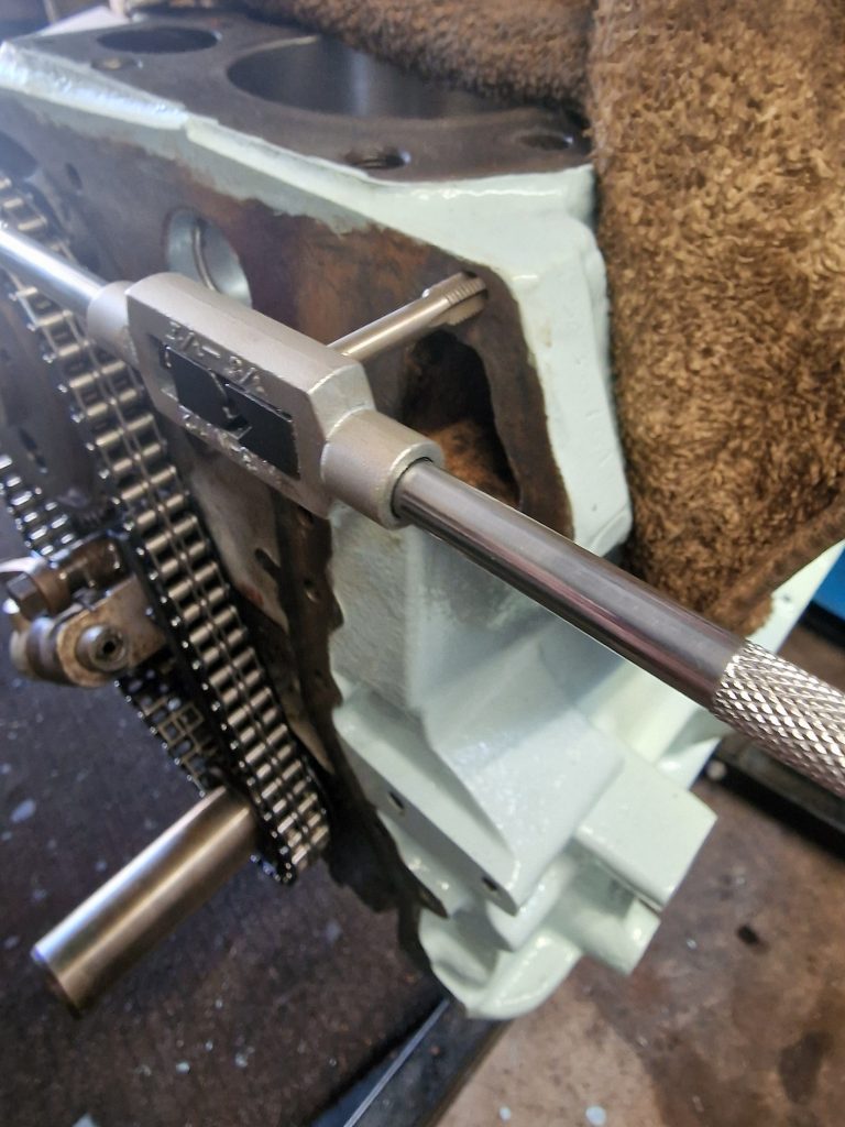
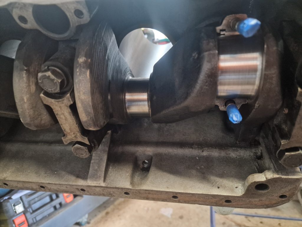
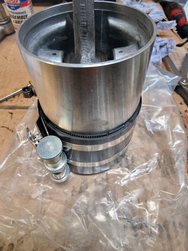
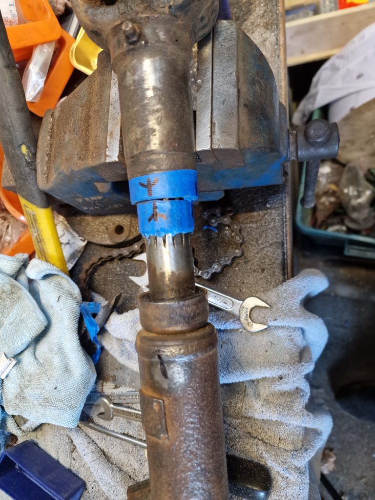
After cleaning then up as much as I could time to take out the old Universal Joints. I tried with a socket and hammer, no luck, so got my borrowed press out. Even with this, it was not easy, kept adding pressure until a couple of them went BANG! as they finally released from the casings. Oh, yes I did take out the circlips before I tried 😉
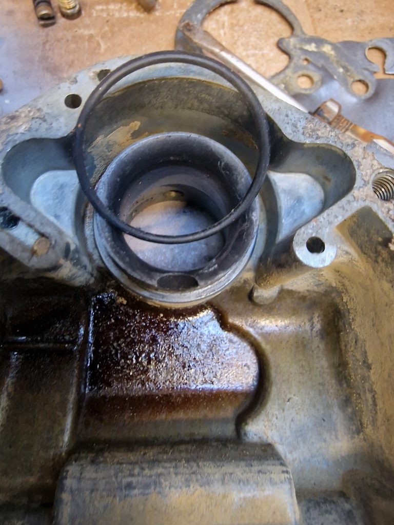
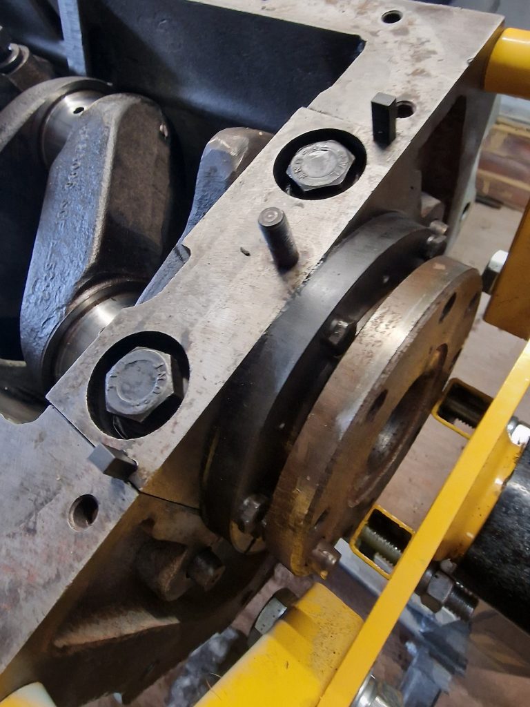
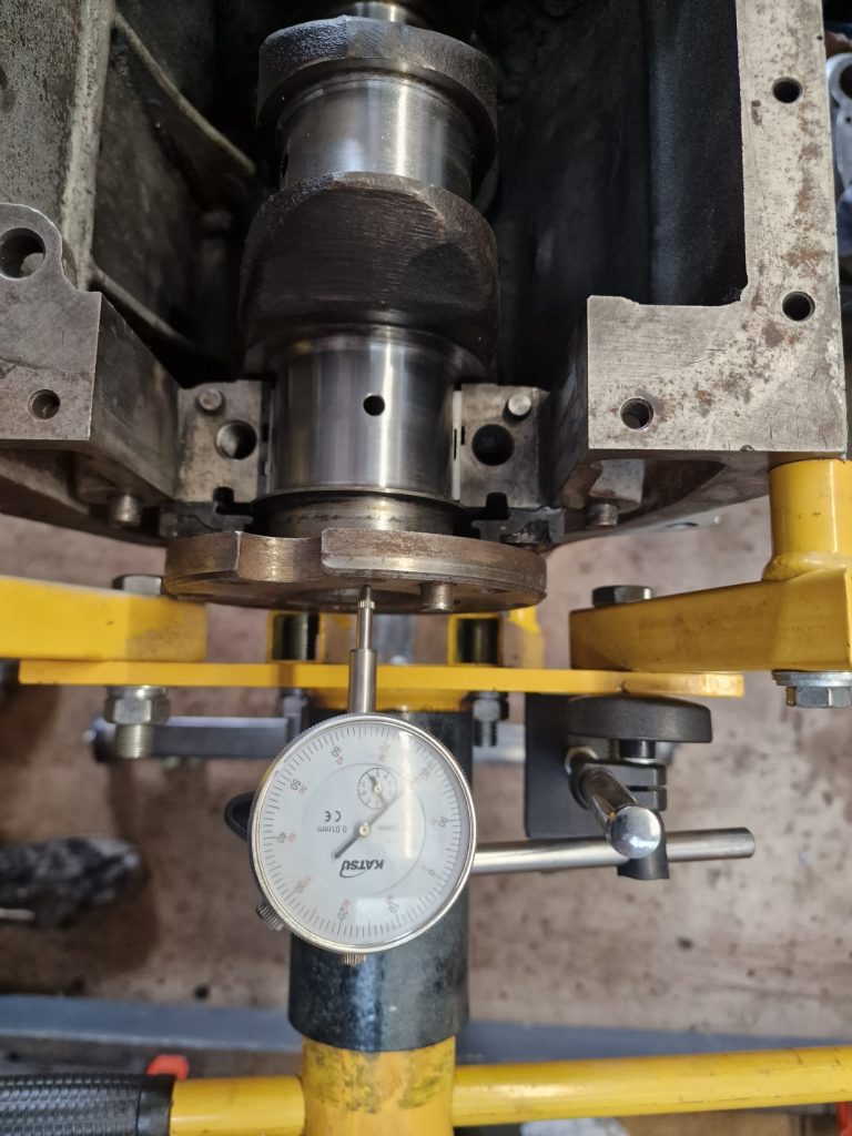
Anyway, same as before, pressed it as far as it would go, took the roller bearing cap off and then pressed it back the other way.
Finally got all 4 out.
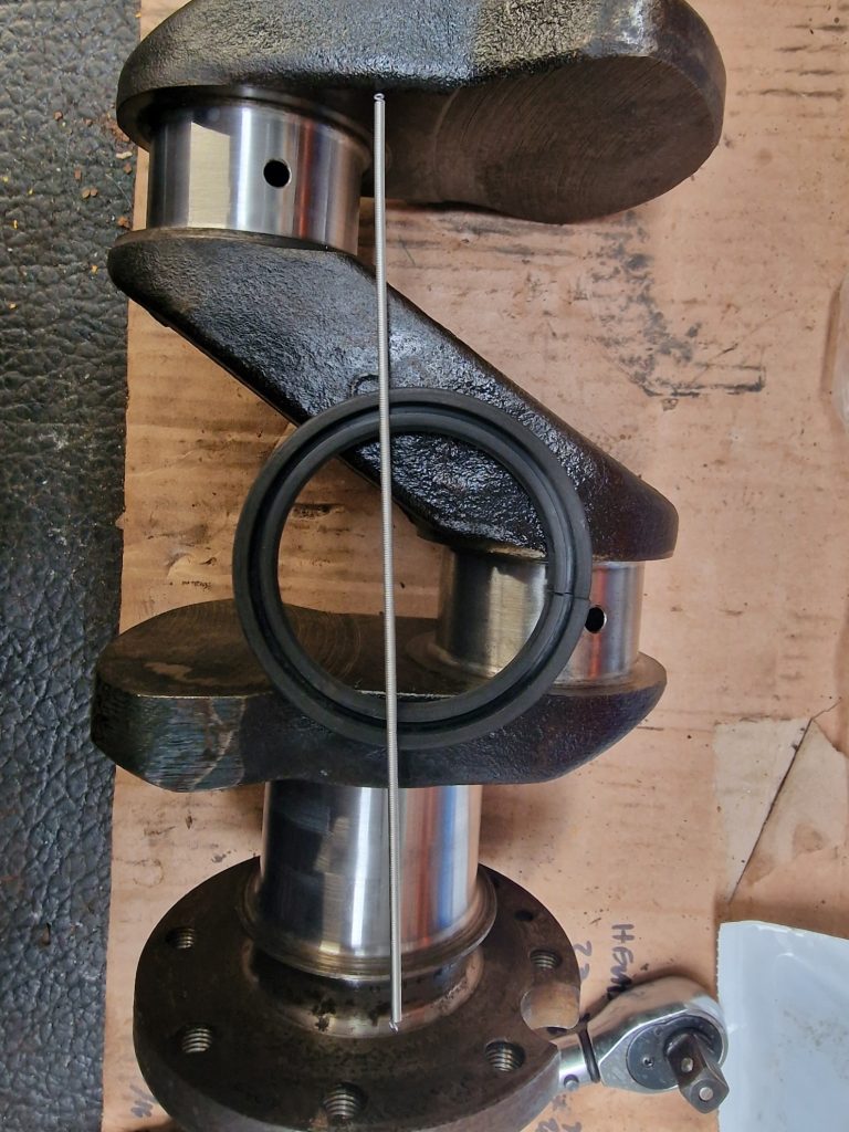
Somehting I did learn before I did this was that they all need to be kept in the same orientation, to maintain as much as possible the balance, so used a little masking take as in the picture, but also stamped the shafts and ends so they can all go back together in exaclty the same way as they came apart.
Went on to then clean the up properly, and got a coat of hammerite – direct to rust black paint.
Cant finish them as dont have the new UJ’s, s onto something else. How about putting some stuff onto the front grill?
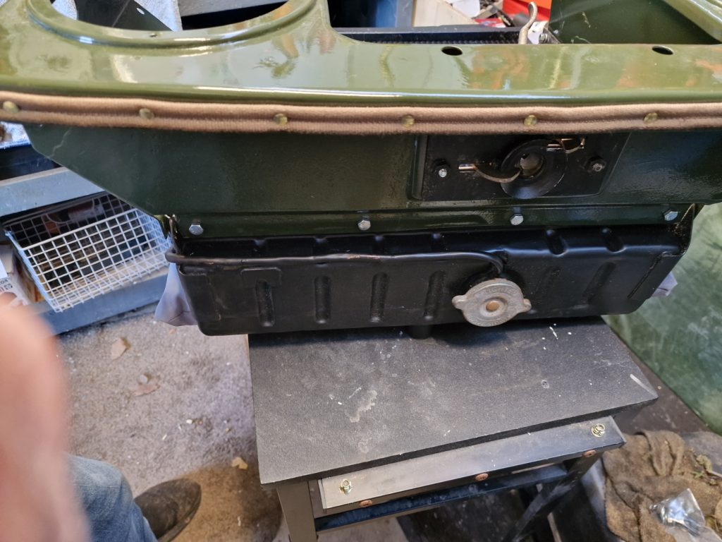
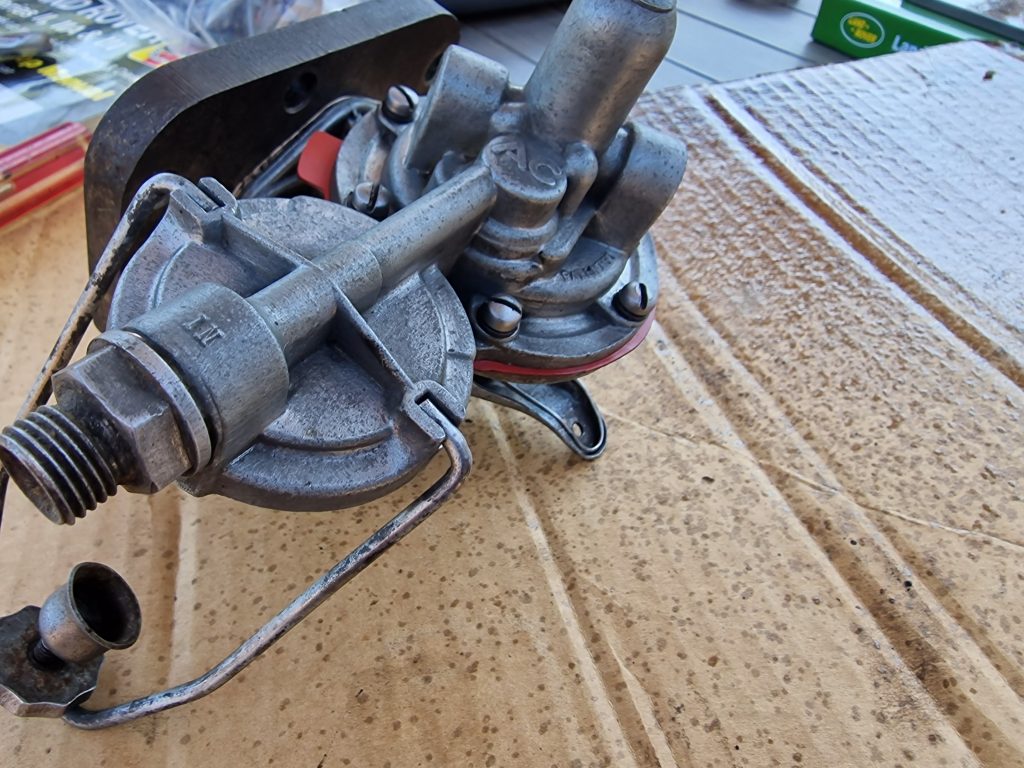
Bolted my new, rather expensive radiator on, added the strip across the top with little rivets (Not sure I got these round the right way, but happy with how it looks) and bolted on the bonnet release machnisum.
So thats now reay to go onto the chassis and be plumbed in for when I try to start the engine.
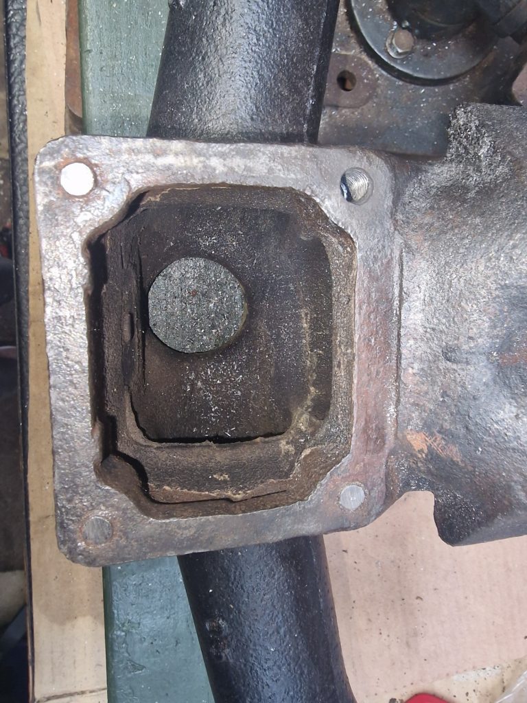
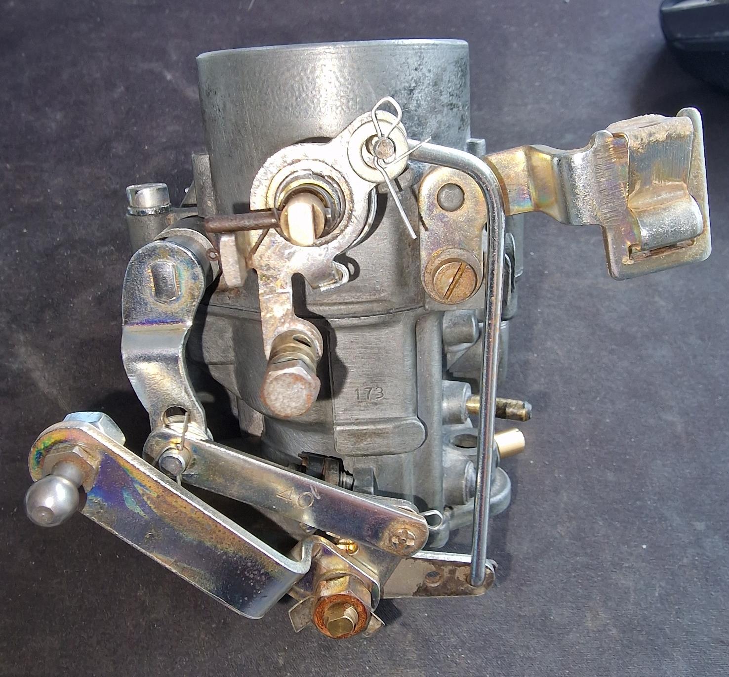
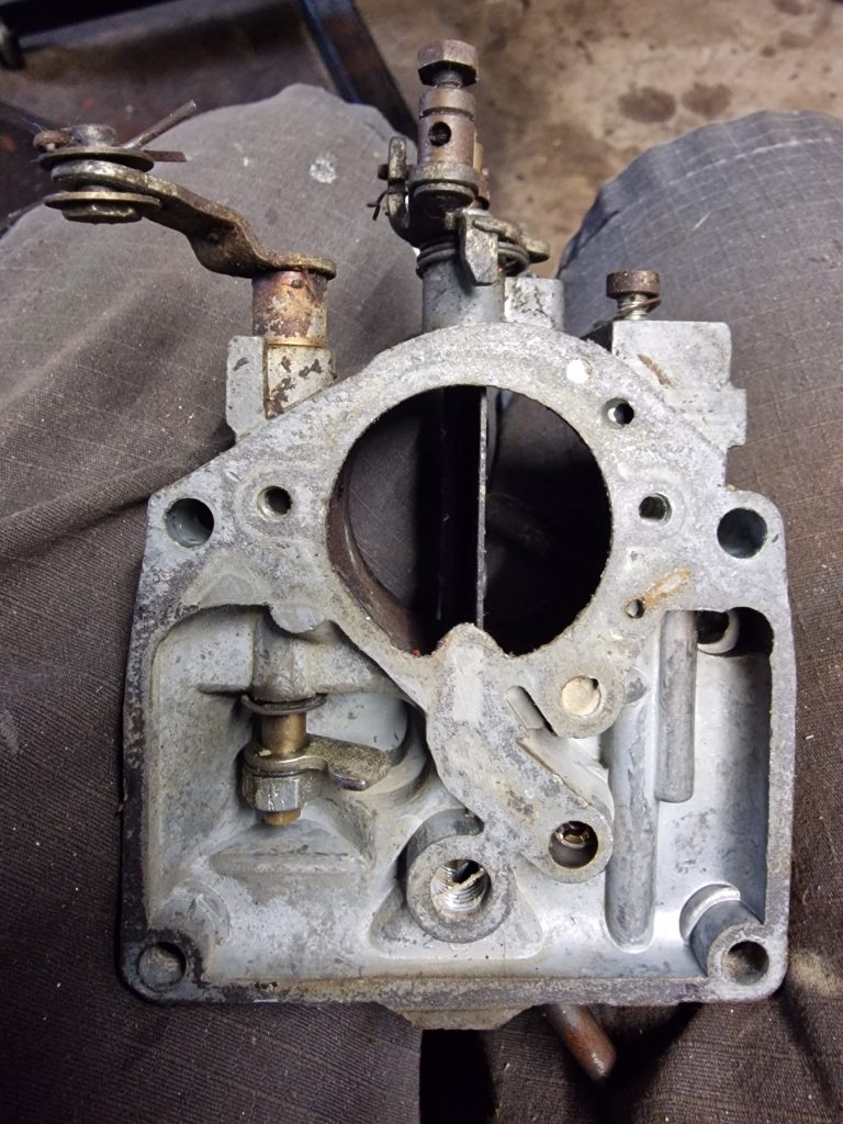
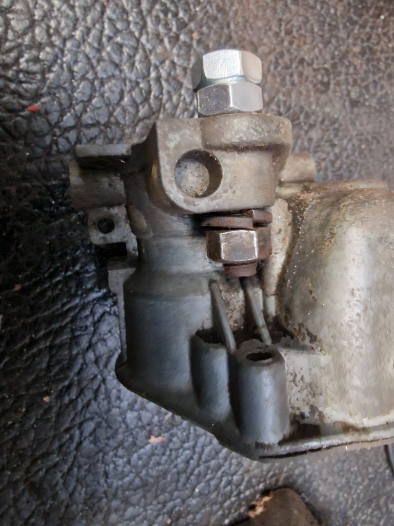
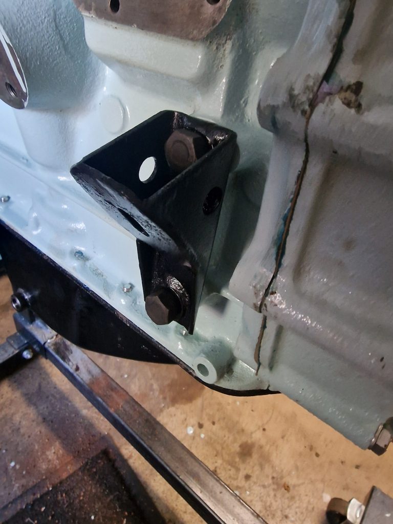
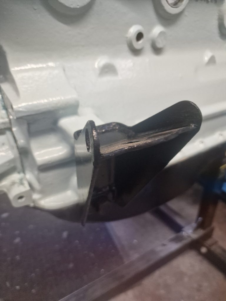
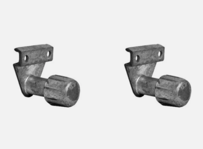
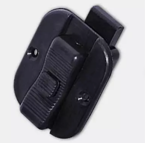
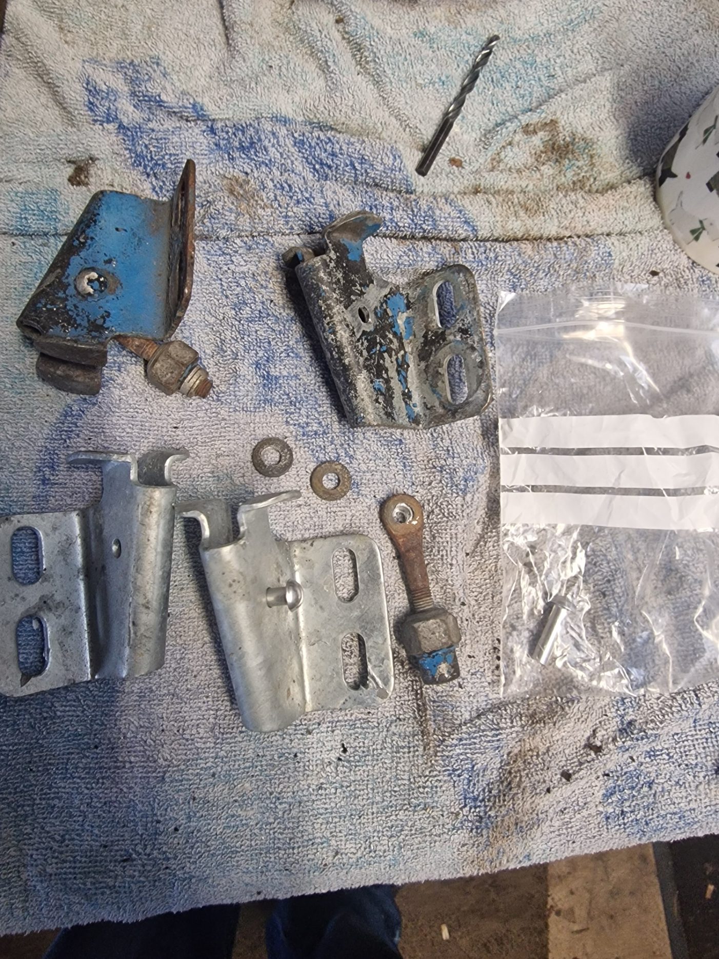
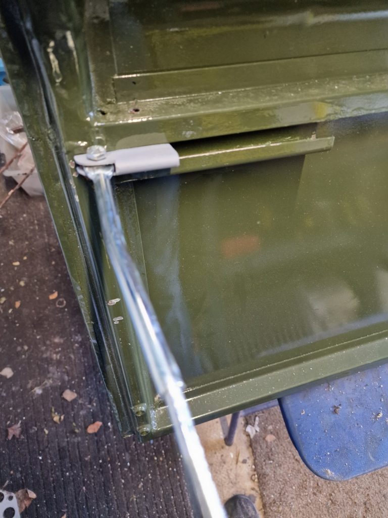
Something I noticed a while ago, but had’nt really thought too much about it was the door stops. Basically its a bar that is located in the bulkhead and attaches to the door, to stop it flying fully open. When I got the Land rover, this never seemed quite right, so investigated.. and this is what I found.
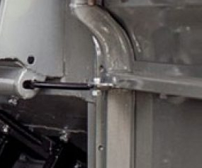
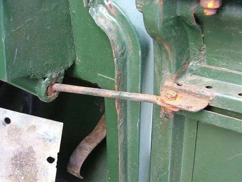
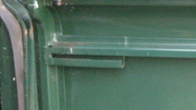
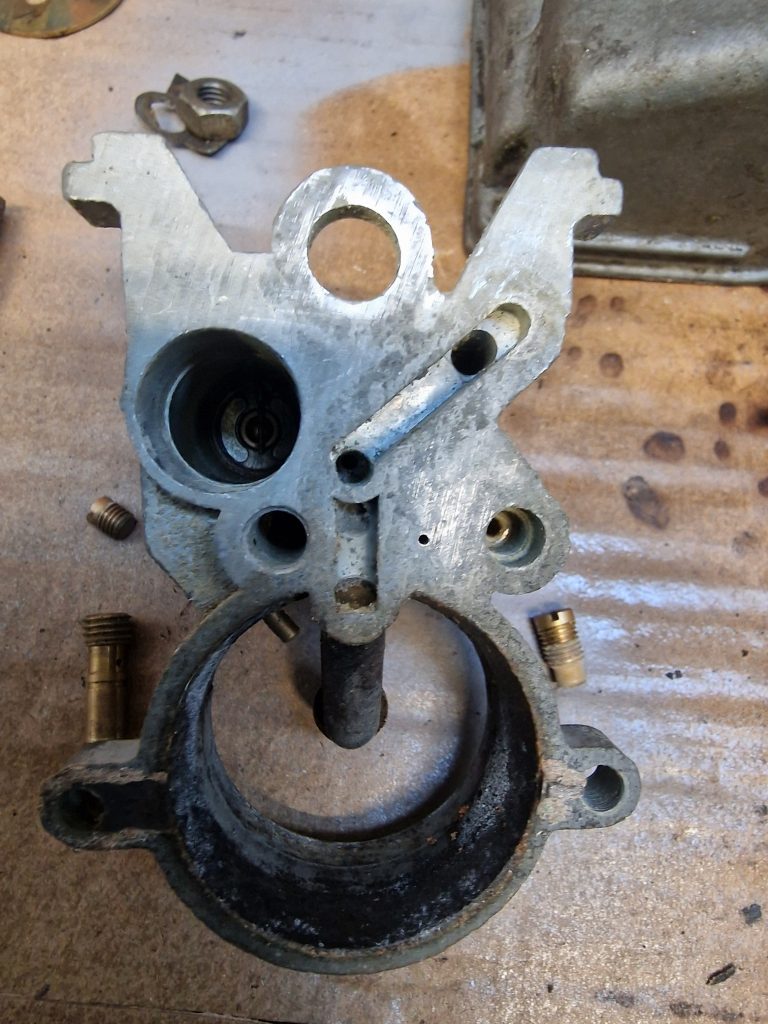
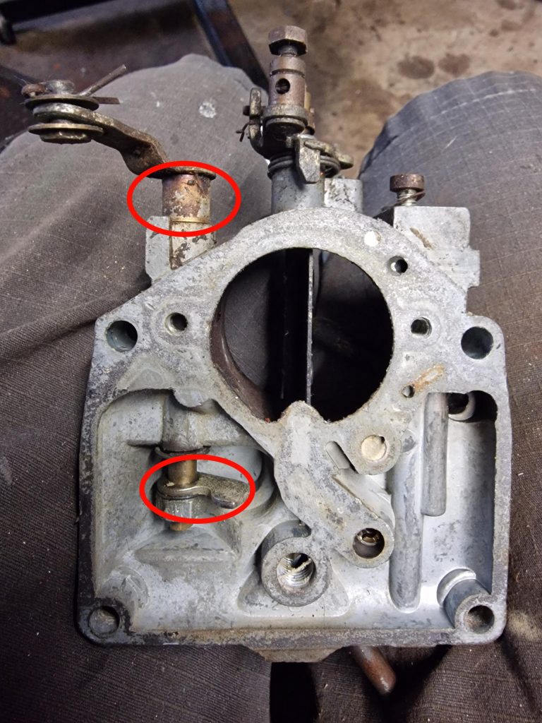
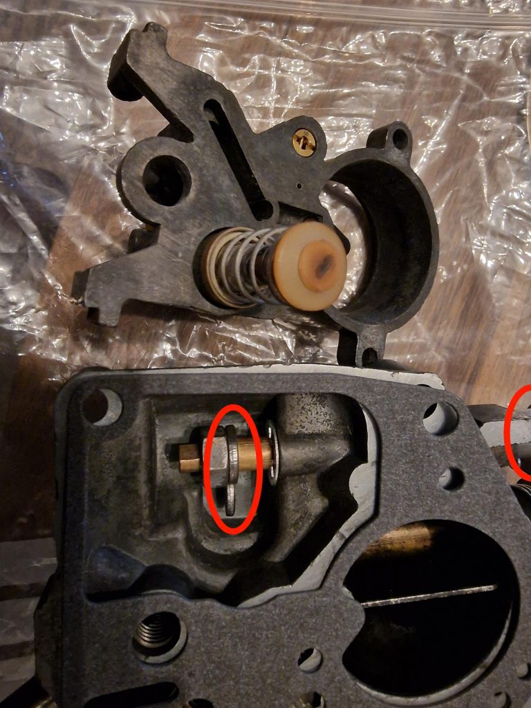
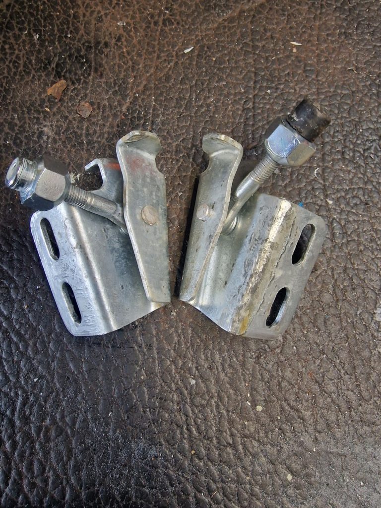
The image on the left and the middle one are actually series 2a doors. The right image is a later series 2a or series 3 door. As can be seen, the door stop mechanisum is a little different. So what do have, I have a series 2a bulkhead and what looks like later or series 3 doors. So I need a way to use the door stops with my seemingly wrong doors! Now, you can buy an adapter for series 3 doors to work with series 2 stops, but while not stupidly expensive, still looking at £30 – £40 for the two, and I have plenty of other stuff to buy, as I will mention later.
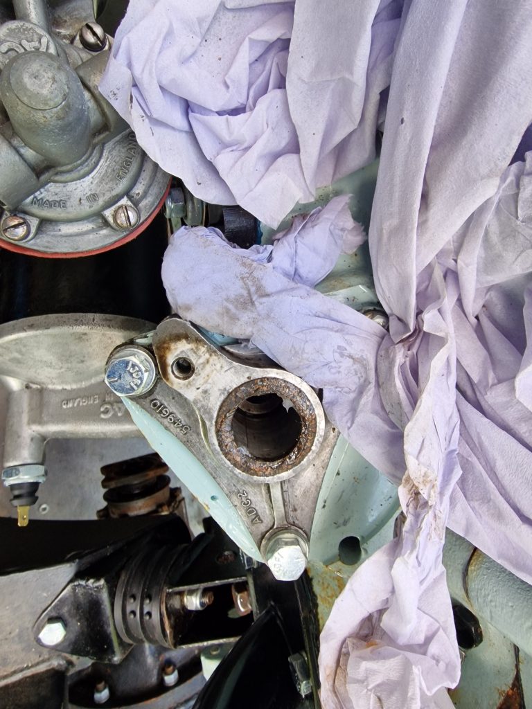
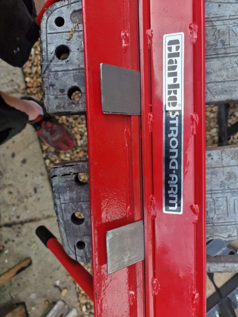
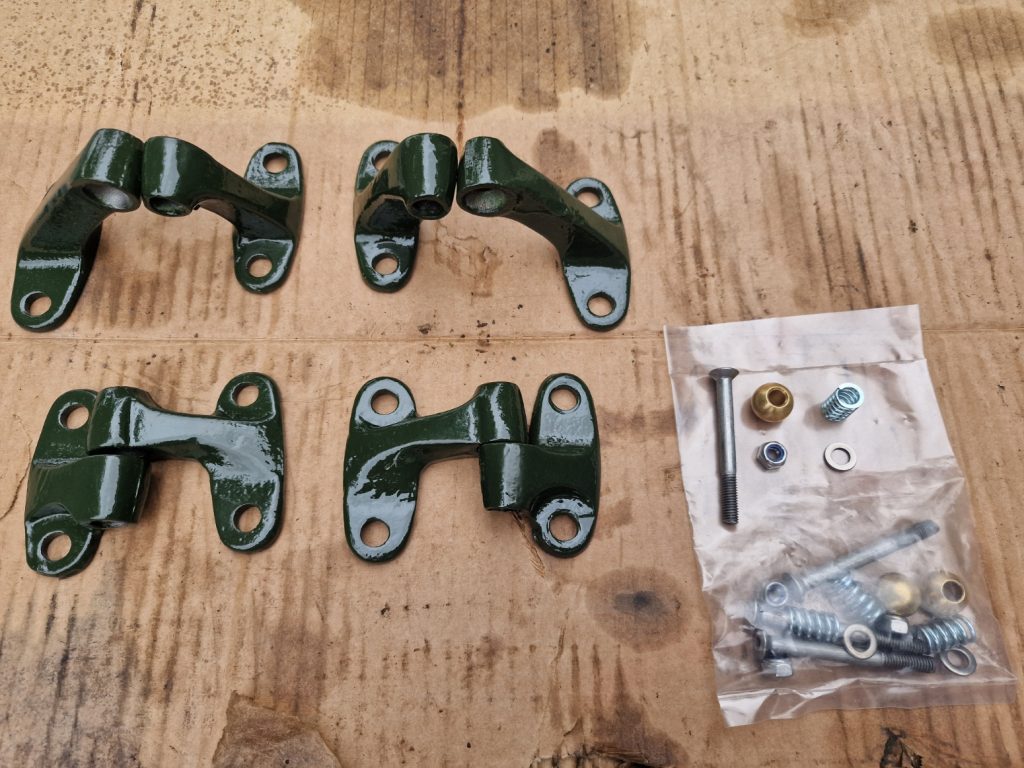
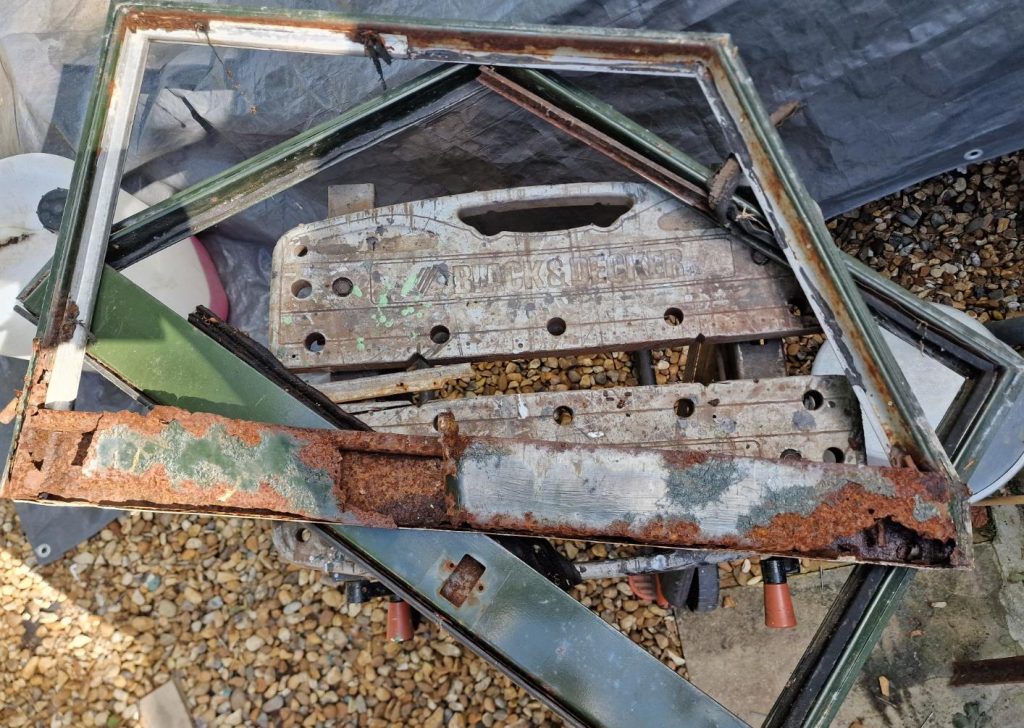
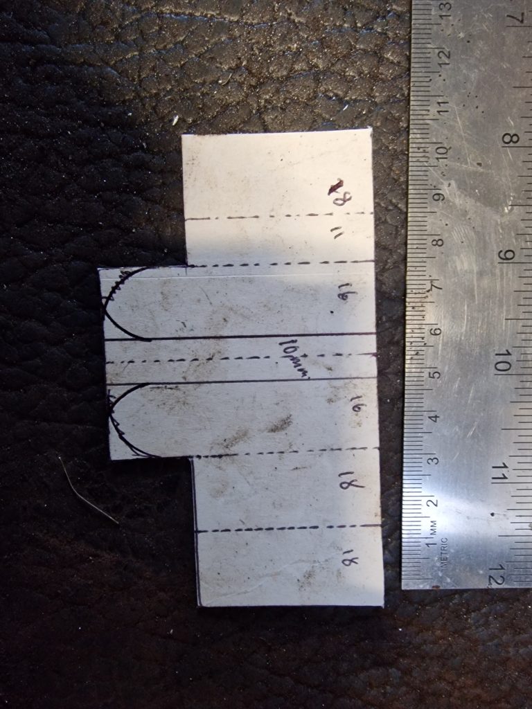
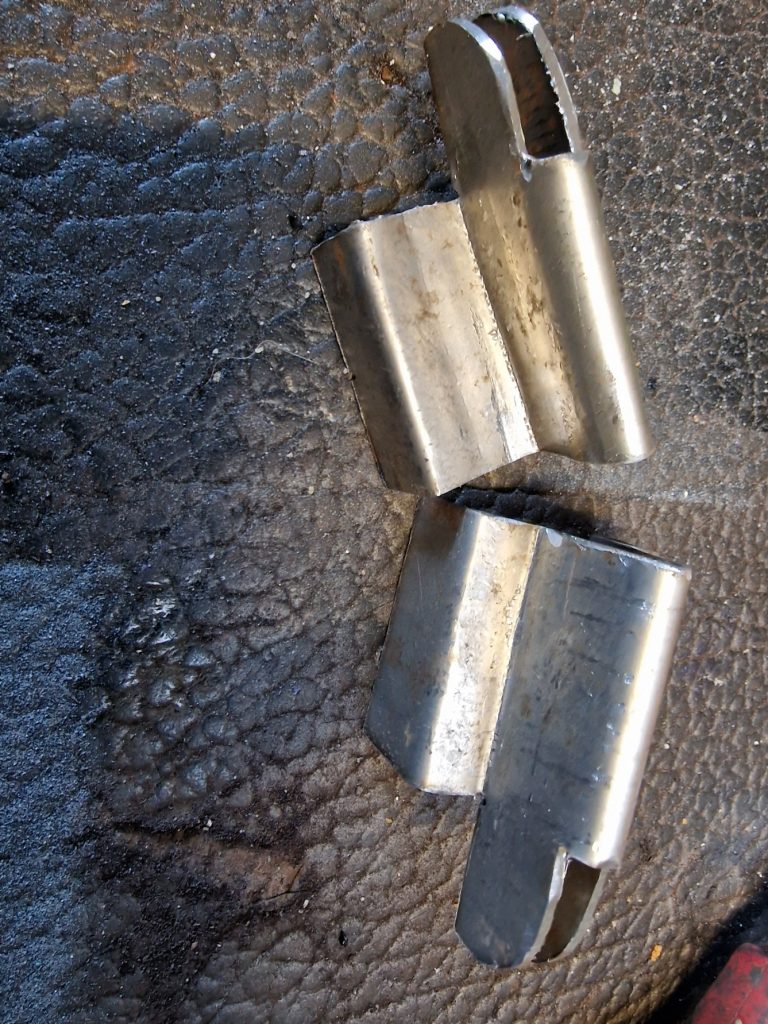
So, I decided to have a go at making some… Bit of 2mm steel sheet, and cardboard template and a little bit of fabrication, I did. Not painted yet, and not finally riveted in, but I think they will work just fine.
You can also see the check strap in the last image, this, as was everthing on this Landy, very crusty, so out came my zinc plating kit and I zinc plated these, and also some other bits an bobs.
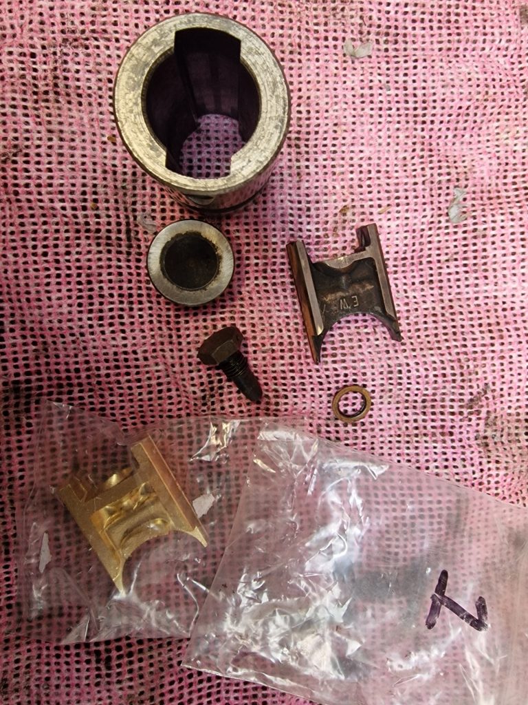
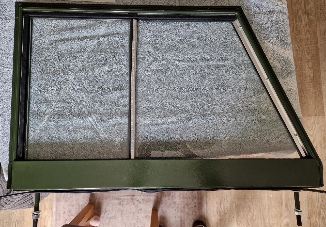
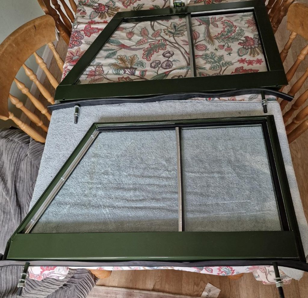
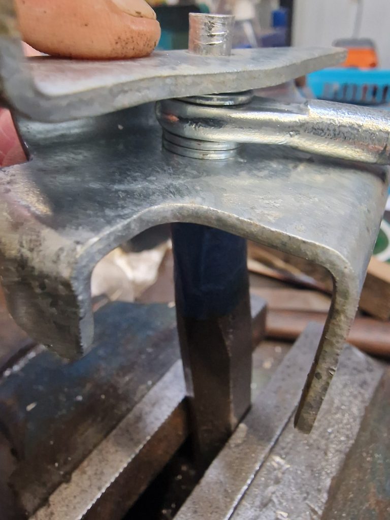
ONe of the other bits I plated was a part of the windscreen locking brackets. Now, when I had the galvanising done, I sent this part also, but didnt realise that a rivet that holds the screw part was aluminium. During gavanizing, which is done at I think 400 degrees, the rivet melted and I lost the screw part!. Cant buy these, and didnt think I could make one, so bought a couple of old parts, took the screw bar off and bought a couple of the rivets. The new/old parts were rust and crudy, so zinc plated them aswell.

Waht I started with, how I riveted them back together, and what i ended up with.
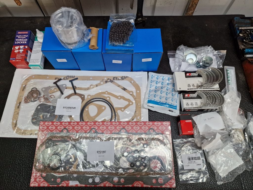
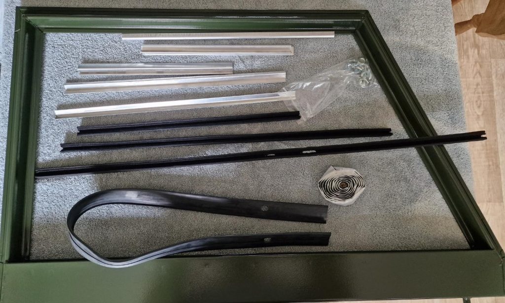
To finish this one up, I have mentioned a few times, Didnt have this or that, all this meant that I placed 3 orders woth my 3 favorite suppliers and bought lots and lots of new bits, including loads of nuts, bolts, wahsers, Propshaft UJ’s, sealer for the windscreen, seals for the rear door / tailgate plus lots of other bits.
Big downside, none of it will turn up until I’m back at work, so will have to continue messing around other bits until I can get some more free time.